How to Use gForceJoint BLE to UART Adapter: Examples, Pinouts, and Specs
Introduction
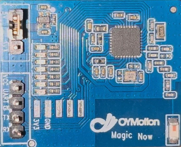
The gForceJoint BLE to UART Adapter, manufactured by Oymotion, is a versatile module designed to bridge Bluetooth Low Energy (BLE) communication with UART interfaces. This adapter allows seamless integration of BLE-enabled devices with microcontrollers, such as the Arduino UNO, enabling wireless data transmission and control. Common applications include wearable devices, remote sensors, and IoT projects where wireless communication is essential.
Explore Projects Built with gForceJoint BLE to UART Adapter

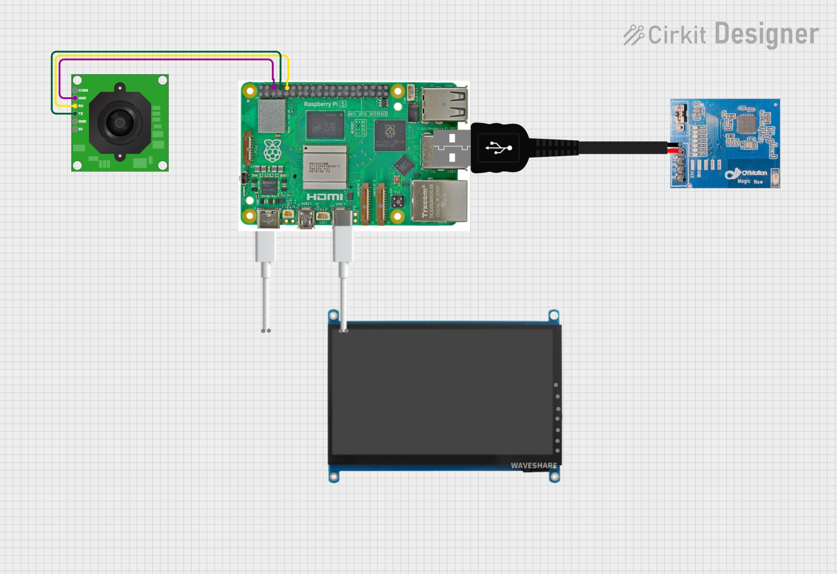
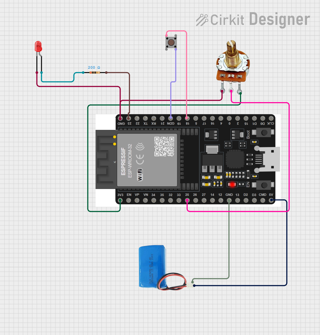

Explore Projects Built with gForceJoint BLE to UART Adapter
Technical Specifications
Key Technical Details
| Parameter | Value |
|---|---|
| Operating Voltage | 3.3V - 5V |
| Current Consumption | 10mA (active), 1mA (idle) |
| Communication | BLE 4.0, UART |
| Baud Rate | 9600 bps (default) |
| Range | Up to 10 meters |
| Dimensions | 25mm x 15mm x 5mm |
Pin Configuration and Descriptions
| Pin Number | Pin Name | Description |
|---|---|---|
| 1 | VCC | Power supply (3.3V - 5V) |
| 2 | GND | Ground |
| 3 | TXD | UART Transmit Data |
| 4 | RXD | UART Receive Data |
| 5 | STATE | Connection status indicator (HIGH when connected) |
Usage Instructions
How to Use the Component in a Circuit
- Power Supply: Connect the VCC pin to a 3.3V or 5V power source and the GND pin to the ground.
- UART Communication: Connect the TXD pin of the adapter to the RX pin of the microcontroller and the RXD pin of the adapter to the TX pin of the microcontroller.
- Status Monitoring: Optionally, connect the STATE pin to an input pin on the microcontroller to monitor the connection status.
Important Considerations and Best Practices
- Ensure the power supply voltage matches the operating voltage range (3.3V - 5V).
- Use appropriate level shifters if interfacing with 5V logic microcontrollers.
- Keep the adapter within the specified range (up to 10 meters) for reliable communication.
- Avoid placing the adapter near sources of electromagnetic interference.
Example: Connecting to an Arduino UNO
Circuit Diagram
gForceJoint BLE to UART Adapter  |  Arduino UNO
---------------------------------|----------------
VCC                              |  5V
GND                              |  GND
TXD                              |  RX (Pin 0)
RXD                              |  TX (Pin 1)
STATE                            |  (Optional) Digital Pin
Sample Arduino Code
#include <SoftwareSerial.h>

// Create a software serial port on pins 2 (RX) and 3 (TX)
SoftwareSerial bleSerial(2, 3);

void setup() {
  // Start the hardware serial port for debugging
  Serial.begin(9600);
  // Start the software serial port for BLE communication
  bleSerial.begin(9600);
  Serial.println("gForceJoint BLE to UART Adapter Initialized");
}

void loop() {
  // Check if data is available from the BLE adapter
  if (bleSerial.available()) {
    // Read the data and send it to the serial monitor
    char data = bleSerial.read();
    Serial.print(data);
  }

  // Check if data is available from the serial monitor
  if (Serial.available()) {
    // Read the data and send it to the BLE adapter
    char data = Serial.read();
    bleSerial.print(data);
  }
}
Troubleshooting and FAQs
Common Issues Users Might Face
- No Data Transmission: Ensure the TX and RX pins are correctly connected and the baud rate is set to 9600 bps.
- Connection Drops: Check for sources of interference and ensure the adapter is within the specified range.
- Power Issues: Verify the power supply voltage and current ratings.
Solutions and Tips for Troubleshooting
- Check Connections: Double-check all wiring and ensure there are no loose connections.
- Monitor Power Supply: Use a stable power supply and avoid using long wires for power connections.
- Use Serial Monitor: Utilize the Arduino Serial Monitor to debug and verify data transmission.
FAQs
Q: Can I use the adapter with a 5V microcontroller? A: Yes, the adapter supports 3.3V to 5V power supply, but ensure proper level shifting for UART communication if needed.
Q: What is the default baud rate? A: The default baud rate is 9600 bps.
Q: How can I check the connection status? A: The STATE pin goes HIGH when a BLE connection is established. You can monitor this pin using a digital input on your microcontroller.
This documentation provides a comprehensive guide to using the gForceJoint BLE to UART Adapter, ensuring both beginners and experienced users can effectively integrate this component into their projects.