Cirkit Designer Logo
Cirkit Designer
Your all-in-one circuit design IDE
Home / 
Component Documentation

How to Use Touch Sensor: Examples, Pinouts, and Specs

Image of Touch Sensor
Cirkit Designer LogoDesign with Touch Sensor in Cirkit Designer

Introduction

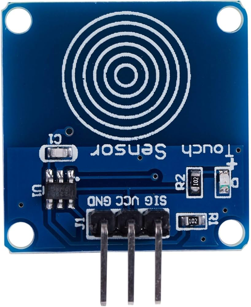
A touch sensor detects physical touch or pressure and converts it into an electrical signal. It is widely used in user interfaces, control systems, and interactive devices. Touch sensors are commonly employed in applications such as touchscreens, home automation systems, robotics, and wearable devices. They provide a simple and intuitive way for users to interact with electronic systems.

Explore Projects Built with Touch Sensor

Use Cirkit Designer to design, explore, and prototype these projects online. Some projects support real-time simulation. Click "Open Project" to start designing instantly!
Arduino UNO Capacitive Touch Sensor Interface
Image of P7Ej2: A project utilizing Touch Sensor in a practical application
This circuit consists of an Arduino UNO microcontroller connected to a capacitive touch sensor. The sensor's VCC and GND pins are powered by the Arduino's 5V and GND pins, respectively, and the sensor's output is connected to the Arduino's digital pin D10. The Arduino can read touch inputs from the sensor to perform various actions based on the provided code.
Cirkit Designer LogoOpen Project in Cirkit Designer
Arduino UNO Touch Sensor Interface
Image of P7Ej3: A project utilizing Touch Sensor in a practical application
This circuit consists of an Arduino UNO microcontroller connected to a capacitive touch sensor. The sensor's VCC and GND pins are connected to the 5V and GND pins of the Arduino, respectively, while the sensor's output pin is connected to digital pin D10 on the Arduino. The setup is designed to detect touch inputs via the sensor and process them using the Arduino.
Cirkit Designer LogoOpen Project in Cirkit Designer
Capacitive Touch and Ultrasonic Sensor Interface with Adafruit Feather nRF52840 Sense
Image of Senior Design Project: A project utilizing Touch Sensor in a practical application
This circuit features an Adafruit Feather nRF52840 Sense microcontroller connected to an ultrasonic sensor for distance measurement and an Adafruit AT42QT1010 capacitive touch sensor for touch input. The ultrasonic sensor's Trigger and Echo pins are interfaced with the microcontroller's digital pins D6 and D9, respectively, to send and receive ultrasonic signals. Additionally, a pressure-sensitive conductive sheet (Velostat) is connected in series with a 10k Ohm resistor to the microcontroller's analog pin A0, likely forming a pressure sensor.
Cirkit Designer LogoOpen Project in Cirkit Designer
Touch Sensor Activated Buzzer with USB Power
Image of Touch Door Bell: A project utilizing Touch Sensor in a practical application
This circuit consists of a touch sensor, a buzzer, and a USB plug for power. When the touch sensor is activated, it triggers the buzzer to sound, powered by the 5V supply from the USB plug.
Cirkit Designer LogoOpen Project in Cirkit Designer

Explore Projects Built with Touch Sensor

Use Cirkit Designer to design, explore, and prototype these projects online. Some projects support real-time simulation. Click "Open Project" to start designing instantly!
Image of P7Ej2: A project utilizing Touch Sensor in a practical application
Arduino UNO Capacitive Touch Sensor Interface
This circuit consists of an Arduino UNO microcontroller connected to a capacitive touch sensor. The sensor's VCC and GND pins are powered by the Arduino's 5V and GND pins, respectively, and the sensor's output is connected to the Arduino's digital pin D10. The Arduino can read touch inputs from the sensor to perform various actions based on the provided code.
Cirkit Designer LogoOpen Project in Cirkit Designer
Image of P7Ej3: A project utilizing Touch Sensor in a practical application
Arduino UNO Touch Sensor Interface
This circuit consists of an Arduino UNO microcontroller connected to a capacitive touch sensor. The sensor's VCC and GND pins are connected to the 5V and GND pins of the Arduino, respectively, while the sensor's output pin is connected to digital pin D10 on the Arduino. The setup is designed to detect touch inputs via the sensor and process them using the Arduino.
Cirkit Designer LogoOpen Project in Cirkit Designer
Image of Senior Design Project: A project utilizing Touch Sensor in a practical application
Capacitive Touch and Ultrasonic Sensor Interface with Adafruit Feather nRF52840 Sense
This circuit features an Adafruit Feather nRF52840 Sense microcontroller connected to an ultrasonic sensor for distance measurement and an Adafruit AT42QT1010 capacitive touch sensor for touch input. The ultrasonic sensor's Trigger and Echo pins are interfaced with the microcontroller's digital pins D6 and D9, respectively, to send and receive ultrasonic signals. Additionally, a pressure-sensitive conductive sheet (Velostat) is connected in series with a 10k Ohm resistor to the microcontroller's analog pin A0, likely forming a pressure sensor.
Cirkit Designer LogoOpen Project in Cirkit Designer
Image of Touch Door Bell: A project utilizing Touch Sensor in a practical application
Touch Sensor Activated Buzzer with USB Power
This circuit consists of a touch sensor, a buzzer, and a USB plug for power. When the touch sensor is activated, it triggers the buzzer to sound, powered by the 5V supply from the USB plug.
Cirkit Designer LogoOpen Project in Cirkit Designer

Technical Specifications

  • Operating Voltage: 2.0V to 5.5V
  • Operating Current: < 20mA
  • Response Time: ~60ms
  • Output Type: Digital (High/Low)
  • Interface: Single output pin
  • Operating Temperature: -20°C to 70°C
  • Sensitivity: Adjustable in some models (varies by manufacturer)

Pin Configuration and Descriptions

Pin Name Description
VCC Power supply pin (2.0V to 5.5V)
GND Ground pin
OUT Digital output pin (High when touched)

Usage Instructions

How to Use the Touch Sensor in a Circuit

  1. Power the Sensor: Connect the VCC pin to a 3.3V or 5V power source and the GND pin to the ground of your circuit.
  2. Connect the Output: Attach the OUT pin to a digital input pin of your microcontroller or to an external circuit that processes the signal.
  3. Test the Sensor: When the sensor is touched, the OUT pin will output a HIGH signal (typically 3.3V or 5V, depending on the supply voltage). When not touched, the output will remain LOW.

Important Considerations and Best Practices

  • Debouncing: The touch sensor may produce noise or false triggers. Use software debouncing techniques to filter out spurious signals.
  • Power Supply: Ensure a stable power supply to avoid erratic behavior.
  • Environmental Factors: Avoid exposing the sensor to extreme temperatures, moisture, or dust, as these can affect its performance.
  • Pull-Down Resistor: If the sensor's output is unstable, consider adding a pull-down resistor (e.g., 10kΩ) to the OUT pin.

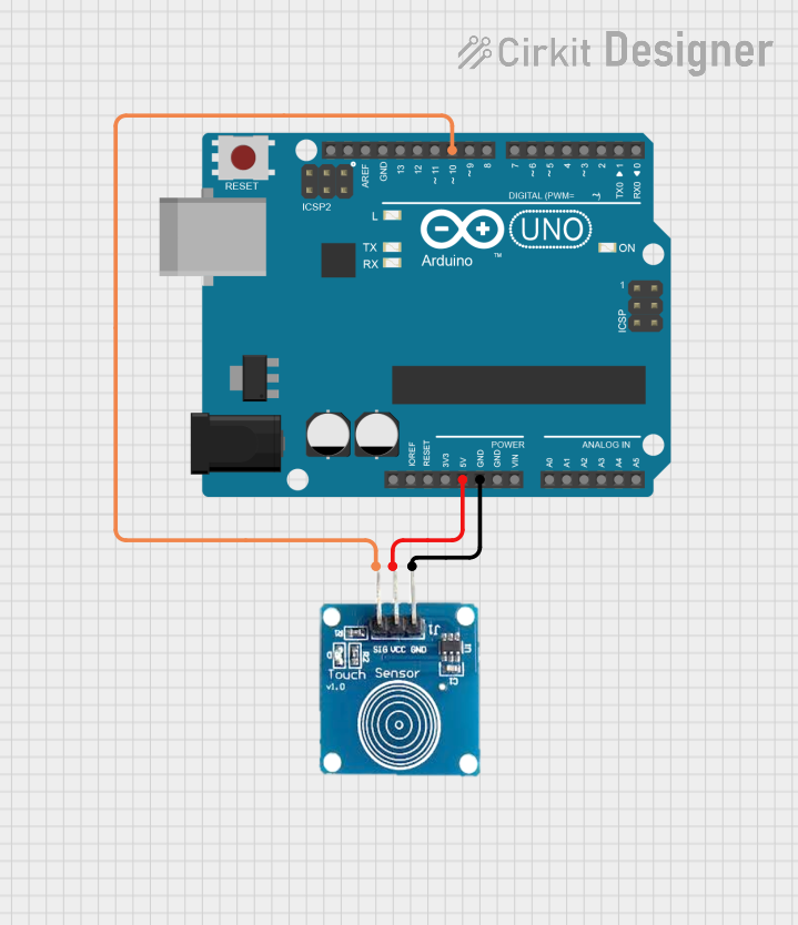
Example: Connecting a Touch Sensor to an Arduino UNO

Below is an example of how to use a touch sensor with an Arduino UNO to control an LED:

// Define pin connections
const int touchPin = 2; // Touch sensor output connected to digital pin 2
const int ledPin = 13;  // LED connected to digital pin 13

void setup() {
  pinMode(touchPin, INPUT); // Set touch sensor pin as input
  pinMode(ledPin, OUTPUT);  // Set LED pin as output
  Serial.begin(9600);       // Initialize serial communication for debugging
}

void loop() {
  int touchState = digitalRead(touchPin); // Read the touch sensor state

  if (touchState == HIGH) {
    // If the sensor is touched, turn on the LED
    digitalWrite(ledPin, HIGH);
    Serial.println("Touch detected! LED ON");
  } else {
    // If not touched, turn off the LED
    digitalWrite(ledPin, LOW);
    Serial.println("No touch detected. LED OFF");
  }

  delay(100); // Small delay to stabilize readings
}

Troubleshooting and FAQs

Common Issues and Solutions

  1. Sensor Not Responding

    • Cause: Incorrect wiring or insufficient power supply.
    • Solution: Double-check the connections and ensure the power supply voltage is within the specified range.
  2. False Triggers

    • Cause: Electrical noise or environmental interference.
    • Solution: Use a pull-down resistor on the OUT pin and ensure proper grounding.
  3. Output Signal is Unstable

    • Cause: Fluctuations in the power supply or poor connections.
    • Solution: Use a decoupling capacitor (e.g., 0.1µF) across the VCC and GND pins to stabilize the power supply.
  4. Touch Sensor is Too Sensitive or Not Sensitive Enough

    • Cause: Sensitivity settings (if adjustable) are not configured properly.
    • Solution: Refer to the manufacturer's datasheet to adjust the sensitivity, if applicable.

FAQs

  • Q: Can I use the touch sensor with a 3.3V microcontroller?
    A: Yes, the touch sensor operates within a voltage range of 2.0V to 5.5V, making it compatible with 3.3V systems.

  • Q: Can the touch sensor detect multiple touches simultaneously?
    A: No, most basic touch sensors are designed to detect a single touch at a time.

  • Q: How do I extend the touch area?
    A: You can attach a conductive material (e.g., aluminum foil) to the sensor's touchpad to increase the touch area. Ensure the material is securely connected and does not short the circuit.

  • Q: Is the touch sensor waterproof?
    A: Most touch sensors are not waterproof. If water resistance is required, consider using a sealed enclosure or a specialized waterproof touch sensor.