How to Use MINI DC 5V 2.4A CHARGE/DISCHARGE MODULE: Examples, Pinouts, and Specs
Introduction
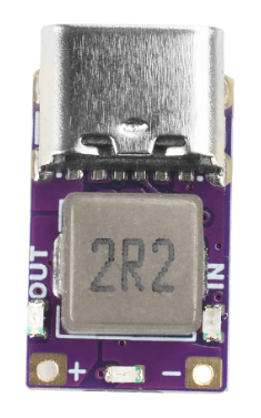
The MINI DC 5V 2.4A CHARGE/DISCHARGE MODULE is a compact and versatile electronic component designed for charging and discharging applications. It operates at a voltage of 5V and can handle a current of up to 2.4A, making it ideal for powering small devices, charging batteries, or integrating into portable power systems. Its small form factor and efficient design make it suitable for a wide range of applications, including DIY electronics projects, power banks, and embedded systems.
Explore Projects Built with MINI DC 5V 2.4A CHARGE/DISCHARGE MODULE


Explore Projects Built with MINI DC 5V 2.4A CHARGE/DISCHARGE MODULE
Common Applications and Use Cases
- Charging lithium-ion or lithium-polymer batteries.
- Powering small electronic devices such as microcontrollers, sensors, or LEDs.
- Integrating into portable power systems like power banks.
- Providing stable 5V output for embedded systems or IoT devices.
Technical Specifications
The following table outlines the key technical details of the MINI DC 5V 2.4A CHARGE/DISCHARGE MODULE:
| Parameter | Specification |
|---|---|
| Input Voltage | 5V DC |
| Output Voltage | 5V DC |
| Maximum Output Current | 2.4A |
| Efficiency | Up to 92% (depending on load) |
| Dimensions | Compact (varies by manufacturer) |
| Operating Temperature | -20°C to +60°C |
| Protection Features | Overcurrent, overvoltage, short-circuit protection |
Pin Configuration and Descriptions
The module typically has the following pin configuration:
| Pin Name | Description |
|---|---|
| VIN | Input voltage pin (5V DC input) |
| GND | Ground pin (common ground for input and output) |
| VOUT | Output voltage pin (5V DC output) |
| CHG | Charging indicator pin (optional, varies by model) |
| EN | Enable pin (optional, used to enable/disable module) |
Usage Instructions
How to Use the Component in a Circuit
- Power Input: Connect a stable 5V DC power source to the
VINpin and the ground of the power source to theGNDpin. - Output Connection: Connect the device or load to the
VOUTpin and its ground to theGNDpin. - Enable Pin (Optional): If the module includes an
ENpin, connect it to a HIGH signal (e.g., 5V) to enable the module or LOW (e.g., GND) to disable it. - Charging Applications: For charging batteries, ensure the battery's voltage and current ratings are compatible with the module's output specifications.
Important Considerations and Best Practices
- Heat Dissipation: Ensure proper ventilation or heat sinking if the module operates near its maximum current (2.4A) for extended periods.
- Input Voltage: Use a stable 5V DC power source to avoid damaging the module or connected devices.
- Load Compatibility: Verify that the connected load does not exceed the module's maximum output current of 2.4A.
- Polarity: Double-check the polarity of connections to avoid short circuits or damage.
Example: Using with an Arduino UNO
The module can be used to power an Arduino UNO or other microcontroller boards. Below is an example of how to connect the module to an Arduino UNO:
- Connect the
VOUTpin of the module to the5Vpin of the Arduino UNO. - Connect the
GNDpin of the module to theGNDpin of the Arduino UNO. - Power the module by connecting a 5V DC input to the
VINpin.
Here is a simple Arduino sketch to blink an LED while powered by the module:
// Simple LED Blink Example
// This code blinks an LED connected to pin 13 of the Arduino UNO.
// Ensure the Arduino is powered by the MINI DC 5V 2.4A CHARGE/DISCHARGE MODULE.

void setup() {
  pinMode(13, OUTPUT); // Set pin 13 as an output pin
}

void loop() {
  digitalWrite(13, HIGH); // Turn the LED on
  delay(1000);            // Wait for 1 second
  digitalWrite(13, LOW);  // Turn the LED off
  delay(1000);            // Wait for 1 second
}
Troubleshooting and FAQs
Common Issues Users Might Face
No Output Voltage:
- Cause: The module may not be receiving power or the
ENpin is not enabled. - Solution: Verify the input voltage at the
VINpin and ensure theENpin is connected to a HIGH signal (if applicable).
- Cause: The module may not be receiving power or the
Overheating:
- Cause: The module is operating near or above its maximum current rating.
- Solution: Reduce the load or improve heat dissipation with a heatsink or better ventilation.
Output Voltage Drops Under Load:
- Cause: The input power source is insufficient or the load exceeds 2.4A.
- Solution: Use a stable 5V DC power source capable of supplying sufficient current.
Short Circuit Protection Triggered:
- Cause: A short circuit occurred on the output side.
- Solution: Disconnect the load, check for wiring issues, and reconnect after resolving the short circuit.
FAQs
Q1: Can this module charge a 3.7V lithium-ion battery?
A1: No, this module outputs a fixed 5V and is not designed for charging 3.7V batteries directly. Use a dedicated lithium-ion battery charging module for such applications.
Q2: Can I use this module with a 12V input?
A2: No, the module is designed for a 5V DC input only. Using a higher input voltage may damage the module.
Q3: Is the module suitable for powering Raspberry Pi boards?
A3: Yes, the module can power Raspberry Pi boards that require 5V and draw less than 2.4A. Ensure the total current consumption of the Raspberry Pi and connected peripherals does not exceed the module's maximum output current.
Q4: Does the module have reverse polarity protection?
A4: This depends on the specific model. Check the datasheet or test carefully. To avoid damage, always double-check the polarity of your connections.