How to Use BUCK CONVERTER: Examples, Pinouts, and Specs
Introduction
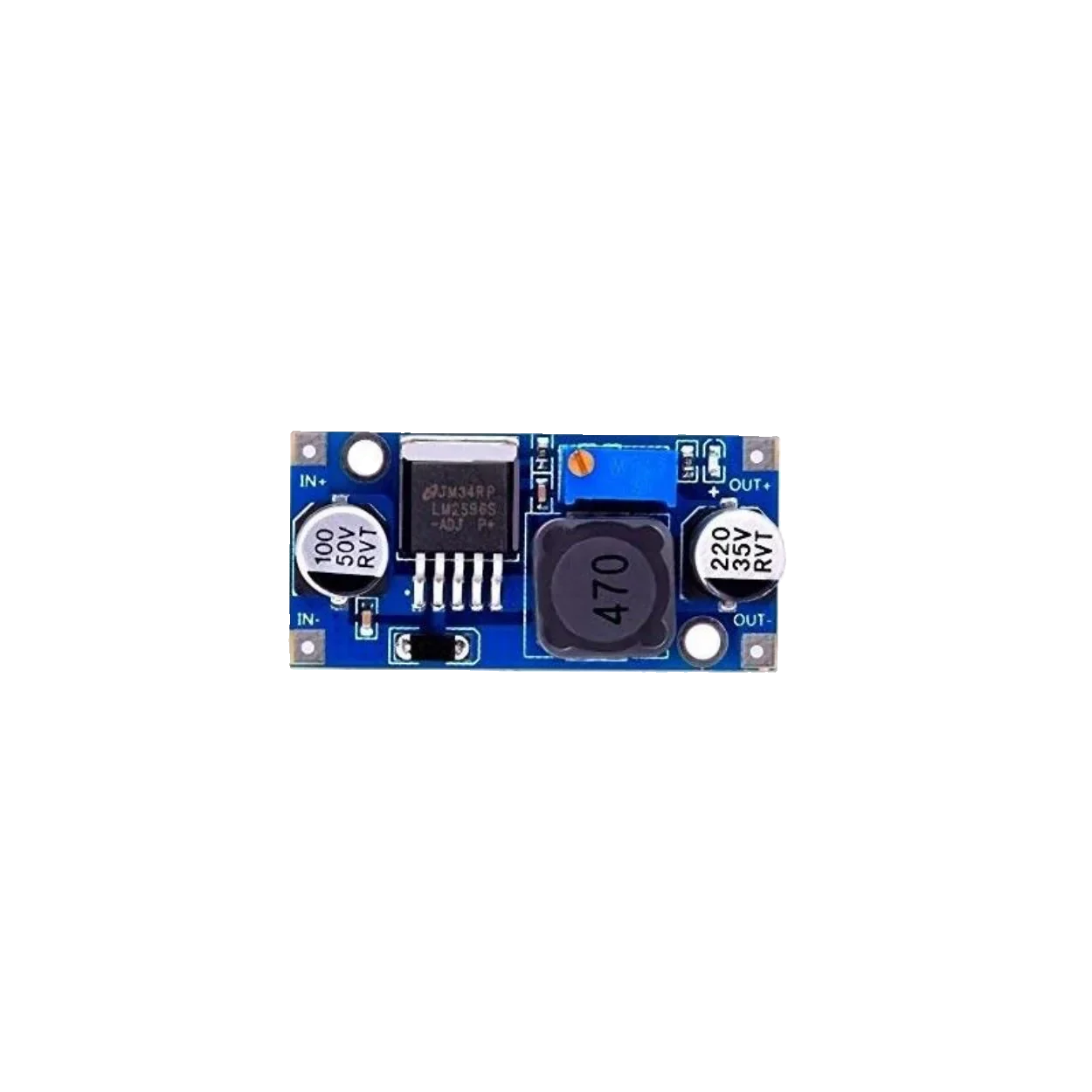
A buck converter is a type of DC-DC converter that steps down voltage while stepping up current. It uses a switching element, a diode, an inductor, and a capacitor to efficiently convert a higher input voltage to a lower output voltage. Buck converters are widely used in power supply systems due to their high efficiency and compact size.
Explore Projects Built with BUCK CONVERTER


Explore Projects Built with BUCK CONVERTER
Common Applications and Use Cases
- Powering low-voltage devices from higher-voltage sources (e.g., 12V to 5V conversion)
- Battery-powered systems to regulate voltage
- Embedded systems and microcontrollers
- LED drivers
- Renewable energy systems (e.g., solar charge controllers)
Technical Specifications
Below are the general technical specifications for a typical buck converter. Note that actual values may vary depending on the specific model.
| Parameter | Value |
|---|---|
| Input Voltage Range | 4.5V to 40V |
| Output Voltage Range | 1.25V to 35V |
| Output Current | Up to 3A (depending on the model) |
| Efficiency | Up to 95% |
| Switching Frequency | 150 kHz |
| Operating Temperature | -40°C to +85°C |
Pin Configuration and Descriptions
The pin configuration of a typical buck converter module is as follows:
| Pin Name | Description |
|---|---|
| VIN | Input voltage pin. Connect the higher input voltage source here. |
| GND | Ground pin. Connect to the ground of the circuit. |
| VOUT | Output voltage pin. Provides the stepped-down voltage to the load. |
| EN (optional) | Enable pin. Used to turn the converter on or off (active high). |
| ADJ (optional) | Adjustment pin. Used to set the output voltage (via a potentiometer or resistor). |
Usage Instructions
How to Use the Buck Converter in a Circuit
Connect the Input Voltage (VIN):
- Connect the positive terminal of the input voltage source to the VIN pin.
- Ensure the input voltage is within the specified range of the buck converter.
Connect the Ground (GND):
- Connect the ground of the input voltage source and the load to the GND pin.
Set the Output Voltage (if adjustable):
- If the buck converter has an adjustable output, use the onboard potentiometer or external resistor to set the desired output voltage.
- Measure the output voltage using a multimeter to ensure accuracy.
Connect the Load to VOUT:
- Connect the positive terminal of the load to the VOUT pin.
- Ensure the load does not exceed the maximum current rating of the buck converter.
Enable the Converter (if applicable):
- If the module has an enable pin, ensure it is connected to a high logic level to activate the converter.
Important Considerations and Best Practices
- Input Voltage: Always ensure the input voltage is higher than the desired output voltage but within the specified range.
- Heat Dissipation: For high-current applications, ensure proper heat dissipation using heatsinks or active cooling.
- Inductor Selection: Use an inductor with the appropriate current rating and low DC resistance for optimal performance.
- Capacitor Selection: Use low-ESR capacitors to minimize voltage ripple.
- Load Regulation: Test the output voltage under load to ensure stability and proper regulation.
Example: Using a Buck Converter with Arduino UNO
Below is an example of using a buck converter to power an Arduino UNO from a 12V source:
- Connect the 12V input to the VIN pin of the buck converter.
- Adjust the output voltage to 5V using the potentiometer.
- Connect the 5V output to the Arduino UNO's 5V pin.
- Connect the GND pin of the buck converter to the Arduino's GND pin.
// Example Arduino code to blink an LED powered by a buck converter
// Ensure the buck converter is providing 5V to the Arduino UNO

const int ledPin = 13; // Pin connected to the onboard LED

void setup() {
  pinMode(ledPin, OUTPUT); // Set the LED pin as an output
}

void loop() {
  digitalWrite(ledPin, HIGH); // Turn the LED on
  delay(1000);                // Wait for 1 second
  digitalWrite(ledPin, LOW);  // Turn the LED off
  delay(1000);                // Wait for 1 second
}
Troubleshooting and FAQs
Common Issues and Solutions
No Output Voltage:
- Cause: Input voltage is not connected or is below the minimum required voltage.
Solution: Verify the input voltage and connections. - Cause: Enable pin is not activated (if applicable).
Solution: Ensure the enable pin is connected to a high logic level.
- Cause: Input voltage is not connected or is below the minimum required voltage.
Output Voltage is Incorrect:
- Cause: Output voltage is not properly adjusted.
Solution: Use a multimeter to measure and adjust the output voltage using the potentiometer. - Cause: Load exceeds the maximum current rating.
Solution: Reduce the load or use a higher-rated buck converter.
- Cause: Output voltage is not properly adjusted.
Excessive Heat:
- Cause: High current draw or poor heat dissipation.
Solution: Add a heatsink or active cooling to the converter.
- Cause: High current draw or poor heat dissipation.
Voltage Ripple or Noise:
- Cause: Insufficient filtering capacitors.
Solution: Add low-ESR capacitors to the input and output.
- Cause: Insufficient filtering capacitors.
FAQs
Q: Can I use a buck converter to power a Raspberry Pi?
A: Yes, but ensure the buck converter can provide a stable 5V output with sufficient current (at least 2.5A for most Raspberry Pi models).
Q: What happens if the input voltage is lower than the output voltage?
A: The buck converter will not function correctly, as it is designed to step down voltage. Use a boost converter for stepping up voltage.
Q: Can I use a buck converter with an AC input?
A: No, buck converters are designed for DC input only. Use a rectifier circuit to convert AC to DC before using a buck converter.