
How to Use Adafruit 16-Channel PWM + Servo HAT: Examples, Pinouts, and Specs
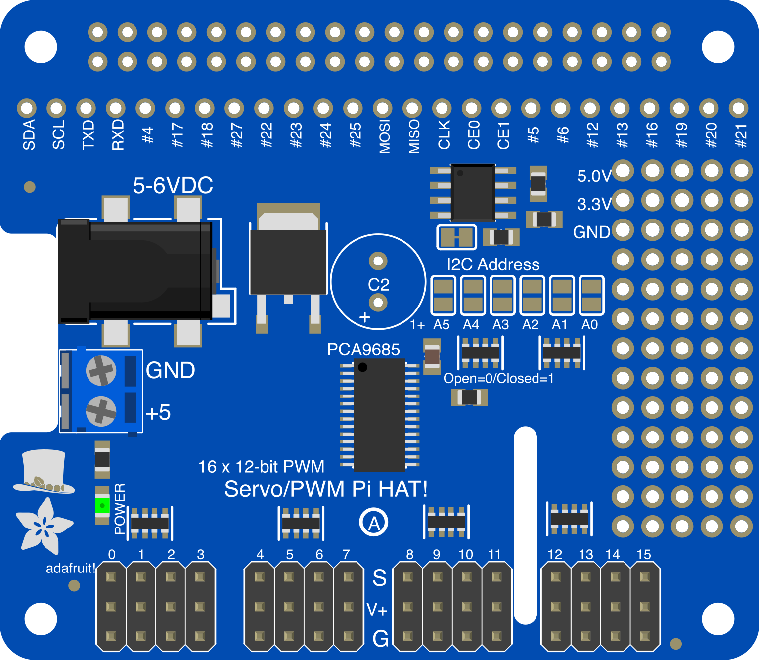
 Design with Adafruit 16-Channel PWM + Servo HAT in Cirkit Designer
Introduction
The Adafruit 16-Channel PWM + Servo HAT (Manufacturer Part ID: 2327) is a versatile add-on board designed for the Raspberry Pi. It provides 16 channels of Pulse Width Modulation (PWM) output, making it ideal for controlling servos, LEDs, and other devices requiring precise timing. This HAT is powered by the PCA9685 PWM driver chip, which communicates with the Raspberry Pi via I2C, allowing for easy integration and control.
Explore Projects Built with Adafruit 16-Channel PWM + Servo HAT
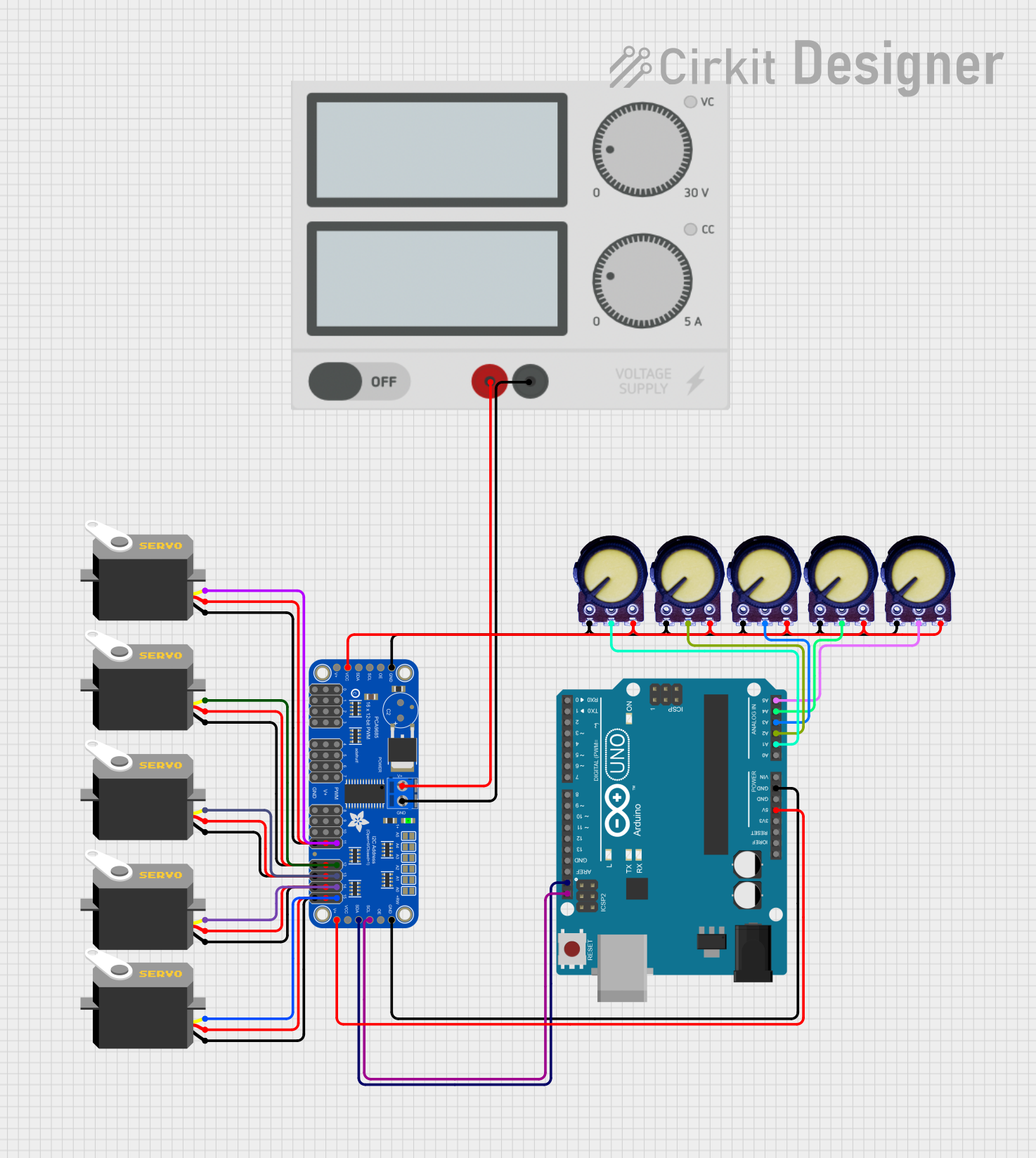 Open Project in Cirkit Designer
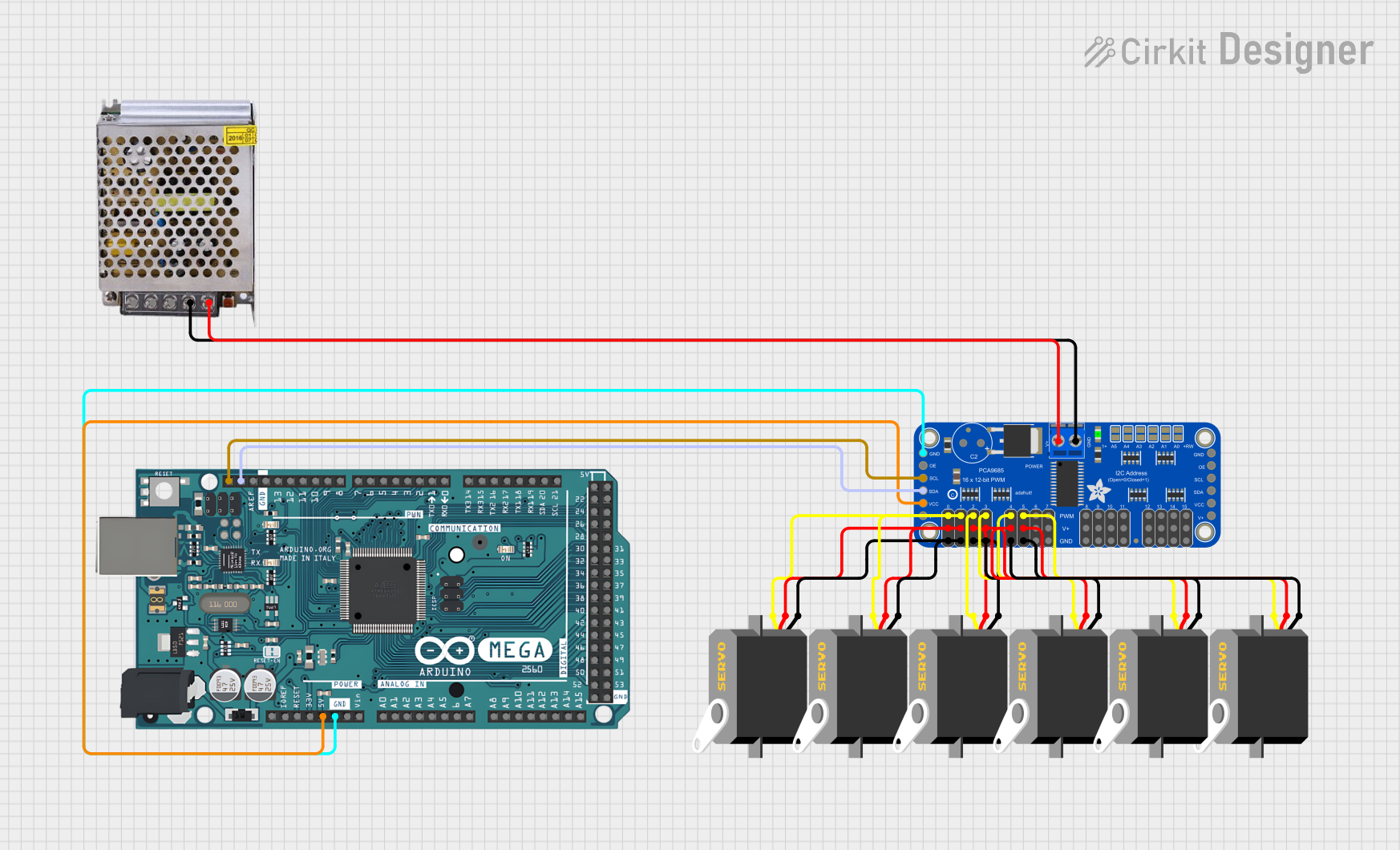 Open Project in Cirkit Designer
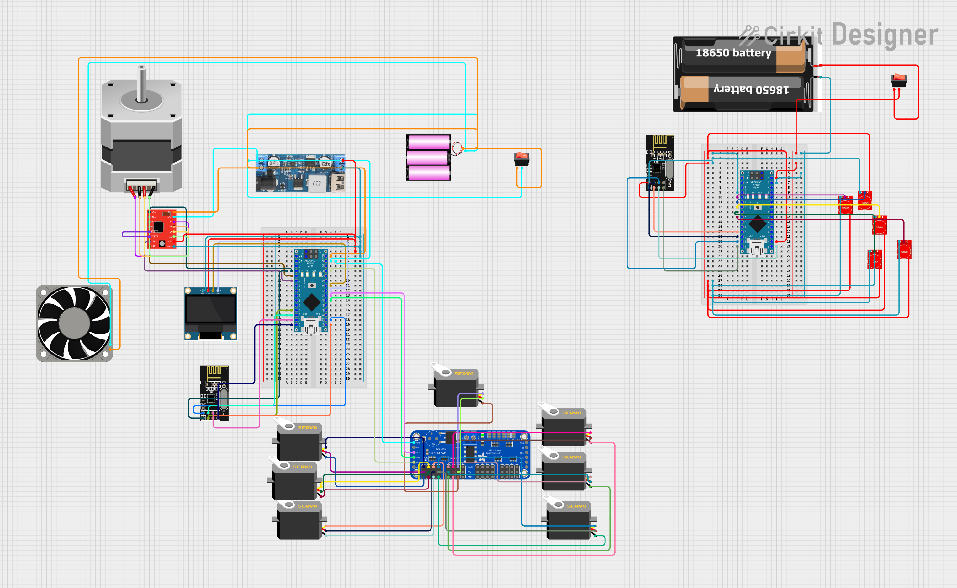 Open Project in Cirkit Designer
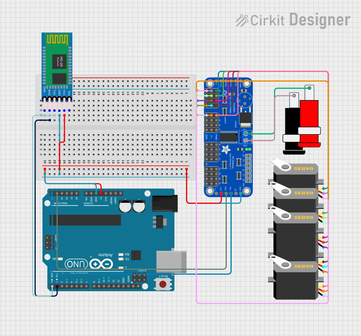 Open Project in Cirkit Designer
Explore Projects Built with Adafruit 16-Channel PWM + Servo HAT
Open Project in Cirkit DesignerOpen Project in Cirkit DesignerOpen Project in Cirkit DesignerOpen Project in Cirkit DesignerCommon Applications and Use Cases
- Robotics: Controlling multiple servo motors for robotic arms, legs, or grippers.
- LED Lighting: Driving multiple LEDs with precise brightness control.
- Animatronics: Coordinating servo movements for lifelike animations.
- Model Railroads: Controlling switches, signals, and other accessories.
- General-purpose PWM control for hobbyist and professional projects.
Technical Specifications
Key Technical Details
- PWM Driver Chip: PCA9685
- Number of Channels: 16 independent PWM outputs
- PWM Resolution: 12-bit (4096 steps)
- Operating Voltage: 3.3V logic (compatible with Raspberry Pi GPIO)
- Power Supply for Servos: 5V-6V (via external power terminal block)
- Communication Protocol: I2C (default address: 0x40, configurable)
- Maximum Frequency: 1.6 kHz
- Dimensions: 65mm x 56mm x 13mm
- Weight: 19g
Pin Configuration and Descriptions
The HAT connects directly to the Raspberry Pi GPIO header and provides additional pins for servo and PWM connections. Below is a description of the key pins and connectors:
GPIO Header (Raspberry Pi Connection)
| Pin Name | Pin Number | Description |
|---|---|---|
| SDA | GPIO 2 | I2C Data Line |
| SCL | GPIO 3 | I2C Clock Line |
| 3.3V | Pin 1 | Power supply for the HAT logic |
| GND | Pin 6 | Ground |
Servo/PWM Output Pins
| Pin Group | Description |
|---|---|
| PWM 0-15 | 16 channels for servo or PWM signal output |
| V+ | External power input for servos (5V-6V) |
| GND | Ground connection for servos and external power |
Power Terminal Block
| Terminal | Description |
|---|---|
| V+ | External power input for servos (5V-6V) |
| GND | Ground connection for external power |
Usage Instructions
How to Use the Component in a Circuit
Attach the HAT to the Raspberry Pi: Align the HAT with the GPIO header on the Raspberry Pi and press it down gently to ensure a secure connection.
Connect Servos or Devices: Plug the servo connectors into the PWM output pins (PWM 0-15). Ensure the correct orientation: signal (white/orange), power (red), and ground (black/brown).
Provide External Power: If driving servos, connect a 5V-6V power supply to the terminal block (V+ and GND). This is necessary to power the servos without overloading the Raspberry Pi.
Install Required Libraries: Use the Adafruit CircuitPython PCA9685 library to control the HAT. Install it using the following command:
pip3 install adafruit-circuitpython-pca9685Write and Run Code: Use Python to control the PWM outputs. Below is an example code snippet to control a servo:
# Import necessary libraries
import time
from board import SCL, SDA
import busio
from adafruit_pca9685 import PCA9685
from adafruit_motor import servo

# Initialize I2C bus and PCA9685 module
i2c = busio.I2C(SCL, SDA)
pca = PCA9685(i2c)
pca.frequency = 50  # Set frequency to 50Hz for servos

# Initialize a servo on channel 0
servo0 = servo.Servo(pca.channels[0])

# Move the servo to different angles
servo0.angle = 0  # Move to 0 degrees
time.sleep(1)     # Wait for 1 second
servo0.angle = 90  # Move to 90 degrees
time.sleep(1)      # Wait for 1 second
servo0.angle = 180  # Move to 180 degrees
time.sleep(1)       # Wait for 1 second

# Turn off the servo
pca.deinit()
Important Considerations and Best Practices
- Power Supply: Always use an external power supply for servos to avoid overloading the Raspberry Pi.
- I2C Address Conflicts: If using multiple I2C devices, ensure they have unique addresses. The PCA9685 address can be changed by soldering the address jumpers on the HAT.
- Servo Current Draw: Check the current draw of your servos to ensure the power supply can handle the load.
- Frequency Setting: Use a frequency of 50Hz for servos. For LEDs or other devices, adjust the frequency as needed.
Troubleshooting and FAQs
Common Issues and Solutions
Servos Not Moving
- Cause: Incorrect power supply or wiring.
- Solution: Verify the external power supply is connected to the terminal block and the servo wires are correctly oriented.
I2C Communication Errors
- Cause: I2C address conflict or improper connection.
- Solution: Check the I2C address of the HAT and ensure no other devices share the same address. Verify the SDA and SCL connections.
Raspberry Pi Not Detecting the HAT
- Cause: I2C interface not enabled.
- Solution: Enable I2C on the Raspberry Pi using
raspi-configand reboot.
PWM Signal Not Stable
- Cause: Incorrect frequency setting.
- Solution: Set the correct frequency for your application (e.g., 50Hz for servos).
FAQs
Can I stack multiple HATs? Yes, you can stack multiple HATs by configuring unique I2C addresses for each HAT.
What is the maximum current the HAT can handle? The HAT itself does not limit current; the external power supply and connected devices determine the maximum current.
Can I use this HAT with other microcontrollers? Yes, the HAT can be used with any microcontroller that supports I2C communication, though it is designed for the Raspberry Pi.
How do I change the I2C address? Solder the address jumpers on the HAT to configure a new I2C address. Refer to the PCA9685 datasheet for address configuration details.