How to Use RELAY SRD-05VDC-SL-C: Examples, Pinouts, and Specs
Introduction
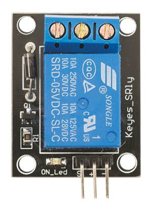
The SRD-05VDC-SL-C is a 5V DC relay module manufactured by SONGLE. It is designed to enable low voltage control signals to switch high voltage devices, making it an essential component in automation, home appliances, and IoT projects. This relay features a Single Pole Double Throw (SPDT) configuration, allowing it to control a circuit by opening or closing its contacts. It is widely used in applications such as motor control, lighting systems, and smart home devices.
Explore Projects Built with RELAY SRD-05VDC-SL-C


Explore Projects Built with RELAY SRD-05VDC-SL-C
Technical Specifications
Below are the key technical details and pin configuration for the SRD-05VDC-SL-C relay:
Key Technical Details
| Parameter | Value |
|---|---|
| Manufacturer | SONGLE |
| Part ID | SRD-05VDC-SL-C |
| Operating Voltage | 5V DC |
| Trigger Voltage | 3.75V DC (minimum) |
| Trigger Current | 70mA |
| Contact Configuration | SPDT (Single Pole Double Throw) |
| Contact Rating | 10A @ 250V AC / 10A @ 30V DC |
| Coil Resistance | 70Ω |
| Insulation Resistance | ≥100MΩ (at 500V DC) |
| Dielectric Strength | 500V AC (between coil and contacts) |
| Operating Temperature | -40°C to +85°C |
| Dimensions | 19mm x 15.5mm x 15mm |
Pin Configuration and Descriptions
The SRD-05VDC-SL-C relay has five pins, as described in the table below:
| Pin Number | Name | Description |
|---|---|---|
| 1 | Coil (+) | Positive terminal of the relay coil. Connect to the control signal (5V DC). |
| 2 | Coil (-) | Negative terminal of the relay coil. Connect to ground (GND). |
| 3 | Common (COM) | Common terminal for the relay switch. |
| 4 | Normally Open (NO) | Open circuit when the relay is inactive; closed when the relay is activated. |
| 5 | Normally Closed (NC) | Closed circuit when the relay is inactive; open when the relay is activated. |
Usage Instructions
How to Use the Component in a Circuit
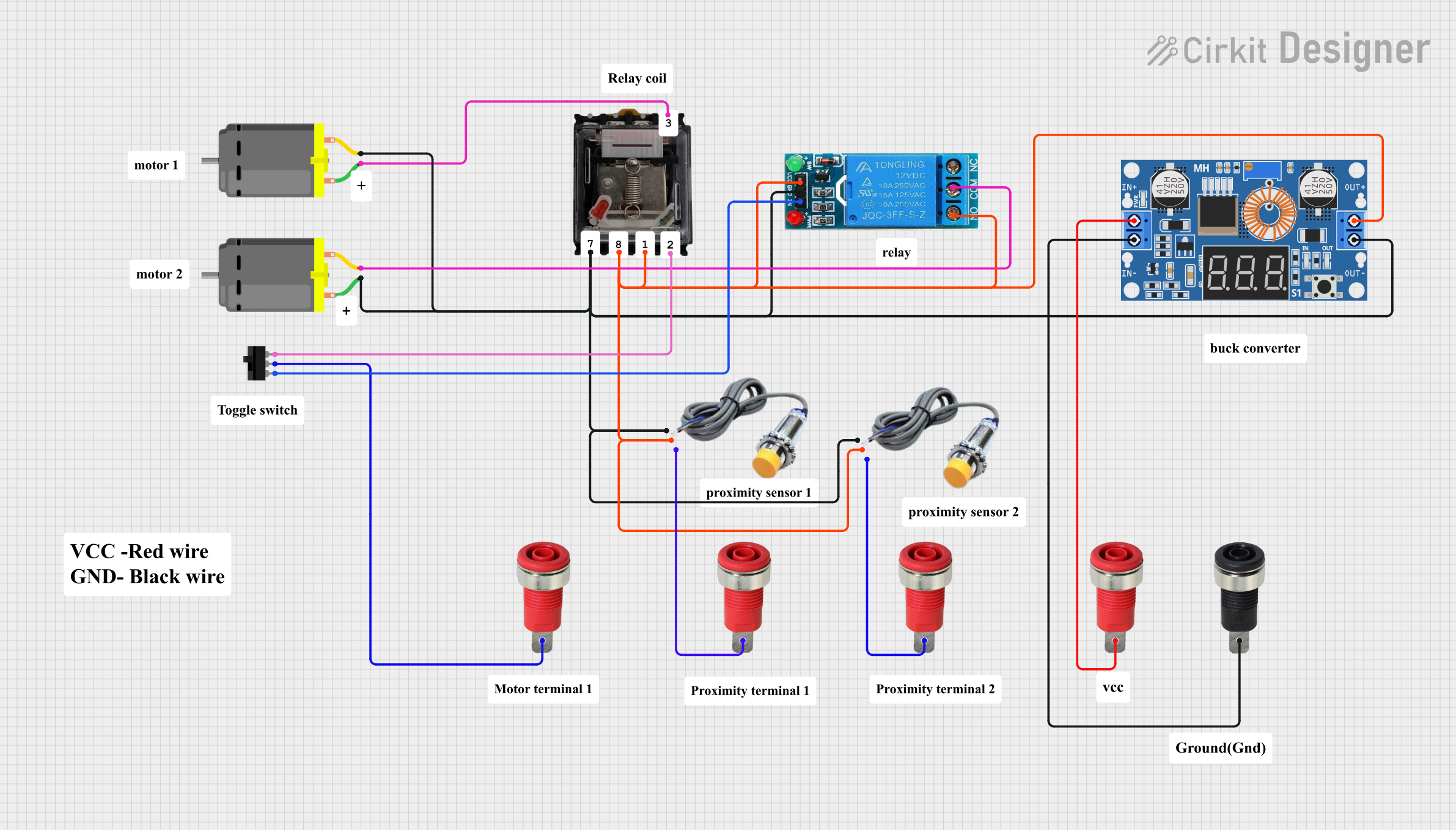
- Power the Relay Coil: Connect the
Coil (+)pin to a 5V DC control signal and theCoil (-)pin to ground. This energizes the relay coil, causing the internal switch to toggle. - Connect the Load:
- For devices that should turn ON when the relay is activated, connect the load between the
Common (COM)andNormally Open (NO)pins. - For devices that should turn OFF when the relay is activated, connect the load between the
Common (COM)andNormally Closed (NC)pins.
- For devices that should turn ON when the relay is activated, connect the load between the
- Control the Relay: Use a microcontroller (e.g., Arduino UNO) or other control circuit to provide the 5V DC signal to the relay coil.
Important Considerations and Best Practices
- Flyback Diode: Always use a flyback diode across the relay coil to protect the control circuit from voltage spikes caused by the collapsing magnetic field when the relay is de-energized.
- Isolation: If switching high voltage devices, ensure proper isolation between the control circuit and the load to prevent damage or hazards.
- Current Rating: Do not exceed the relay's contact rating (10A @ 250V AC or 10A @ 30V DC) to avoid overheating or damage.
- Secure Connections: Ensure all connections are secure to prevent arcing or loose contacts.
Example: Connecting to an Arduino UNO
Below is an example of how to control the SRD-05VDC-SL-C relay using an Arduino UNO:
Circuit Connections
- Connect the
Coil (+)pin of the relay to Arduino digital pin 7. - Connect the
Coil (-)pin of the relay to Arduino GND. - Connect the load (e.g., a light bulb) between the
Common (COM)andNormally Open (NO)pins. - Use an external power source for the load if required.
Arduino Code
// Define the relay control pin
const int relayPin = 7;

void setup() {
  // Set the relay pin as an output
  pinMode(relayPin, OUTPUT);
  // Ensure the relay is off at startup
  digitalWrite(relayPin, LOW);
}

void loop() {
  // Turn the relay ON (activates the load)
  digitalWrite(relayPin, HIGH);
  delay(5000); // Keep the relay ON for 5 seconds

  // Turn the relay OFF (deactivates the load)
  digitalWrite(relayPin, LOW);
  delay(5000); // Keep the relay OFF for 5 seconds
}
Troubleshooting and FAQs
Common Issues and Solutions
Relay Not Activating:
- Cause: Insufficient voltage or current to the relay coil.
- Solution: Ensure the control signal provides at least 3.75V DC and 70mA current.
Load Not Switching:
- Cause: Incorrect wiring of the load to the relay pins.
- Solution: Verify the load is connected to the correct pins (
COM,NO, orNC) based on the desired behavior.
Relay Buzzing Noise:
- Cause: Insufficient or unstable power supply to the relay coil.
- Solution: Use a stable 5V DC power source and ensure proper connections.
Overheating:
- Cause: Exceeding the relay's contact rating.
- Solution: Ensure the load does not draw more than 10A or operate at voltages higher than 250V AC or 30V DC.
FAQs
Can I use the SRD-05VDC-SL-C with a 3.3V control signal?
- No, the relay requires a minimum of 3.75V DC to activate reliably. Use a level shifter or transistor circuit if your control signal is 3.3V.
Is the relay suitable for switching DC motors?
- Yes, but ensure the motor's current and voltage are within the relay's contact rating. Use a flyback diode across the motor terminals to protect the relay.
Can I use this relay for AC loads?
- Yes, the relay can handle up to 10A at 250V AC. Ensure proper isolation and safety precautions when working with AC loads.