How to Use lcd tutroial: Examples, Pinouts, and Specs
Introduction
Liquid Crystal Displays (LCDs) are widely used in electronic projects to visually display information such as text, numbers, and custom characters. These displays are energy-efficient, easy to interface with microcontrollers, and come in various sizes and configurations. The most common type is the 16x2 LCD, which can display 16 characters per line across two rows.
LCDs are commonly used in:
- DIY electronics projects
- Embedded systems
- Home automation systems
- Industrial control panels
- Educational tools for learning microcontroller programming
This tutorial provides a comprehensive guide on how to use and implement LCDs in your projects, including wiring, programming, and troubleshooting.
Explore Projects Built with lcd tutroial
Explore Projects Built with lcd tutroial
Technical Specifications
Below are the key technical details for a standard 16x2 LCD module:
| Parameter | Value |
|---|---|
| Operating Voltage | 4.7V to 5.3V |
| Operating Current | 1mA (without backlight) |
| Backlight Current | ~15mA |
| Display Type | Alphanumeric |
| Character Size | 5x8 dot matrix |
| Interface Type | Parallel (4-bit or 8-bit) |
| Number of Pins | 16 |
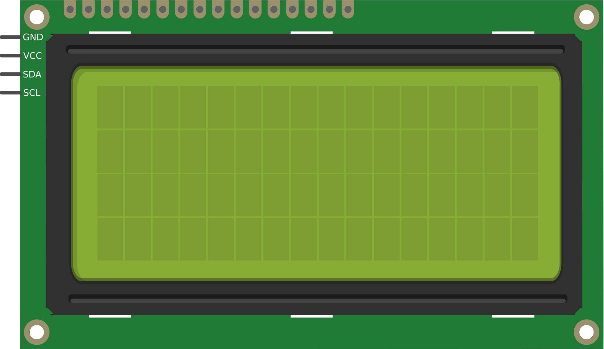
Pin Configuration and Descriptions
The 16x2 LCD module has 16 pins, as described in the table below:
| Pin Number | Pin Name | Description |
|---|---|---|
| 1 | VSS | Ground (0V) connection |
| 2 | VDD | Power supply (4.7V to 5.3V) |
| 3 | V0 | Contrast adjustment (connect to a potentiometer) |
| 4 | RS | Register Select: 0 = Command mode, 1 = Data mode |
| 5 | RW | Read/Write: 0 = Write, 1 = Read (commonly tied to ground for write-only mode) |
| 6 | E | Enable pin: Triggers data read/write when toggled |
| 7-14 | D0-D7 | Data pins: Used to send data/commands (4-bit or 8-bit mode) |
| 15 | LED+ | Backlight anode (connect to 5V via a resistor) |
| 16 | LED- | Backlight cathode (connect to ground) |
Usage Instructions
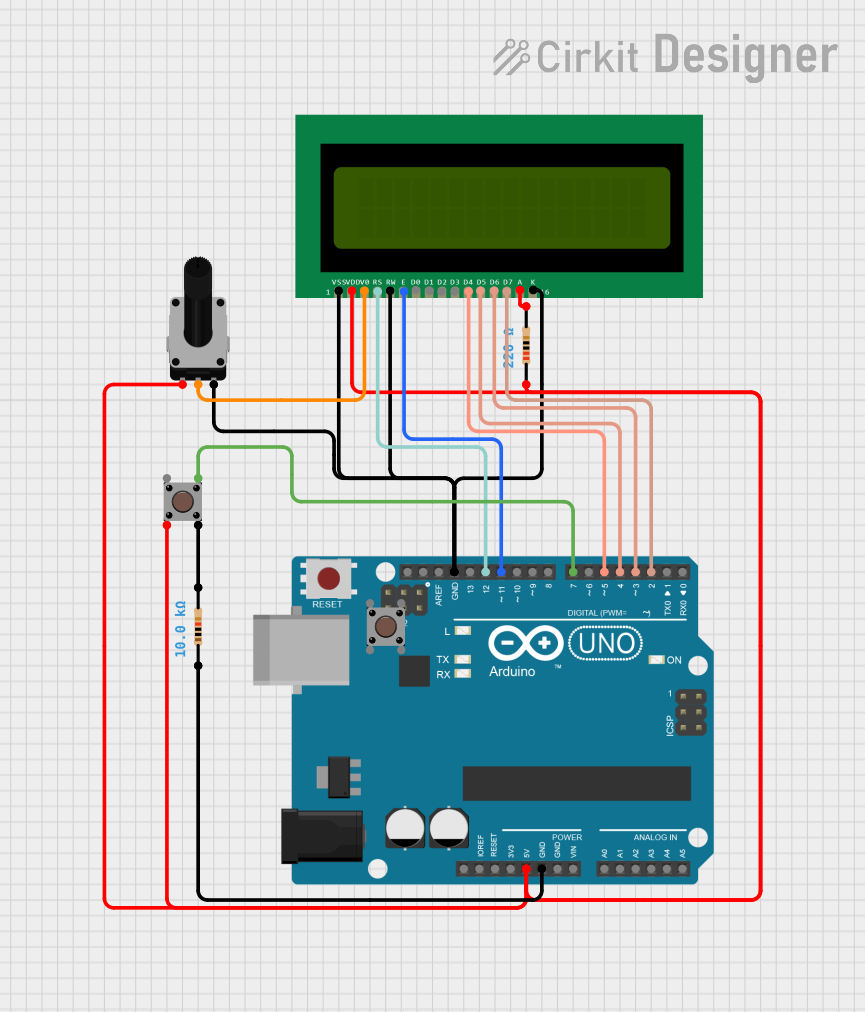
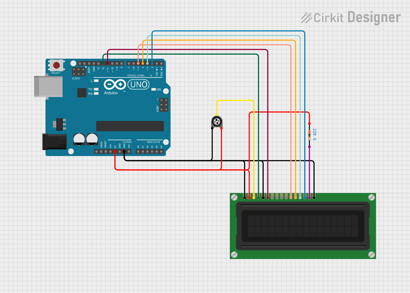
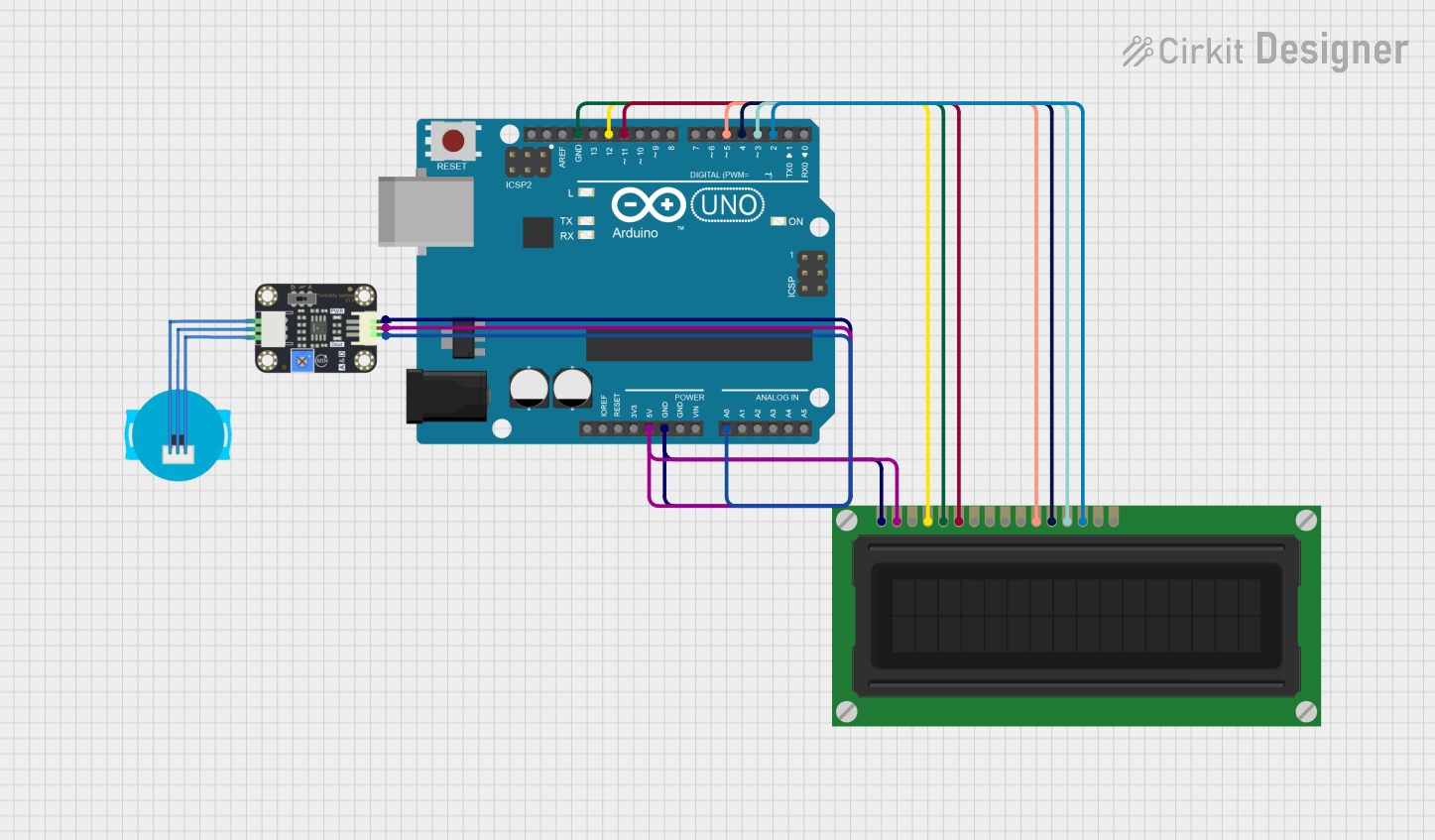
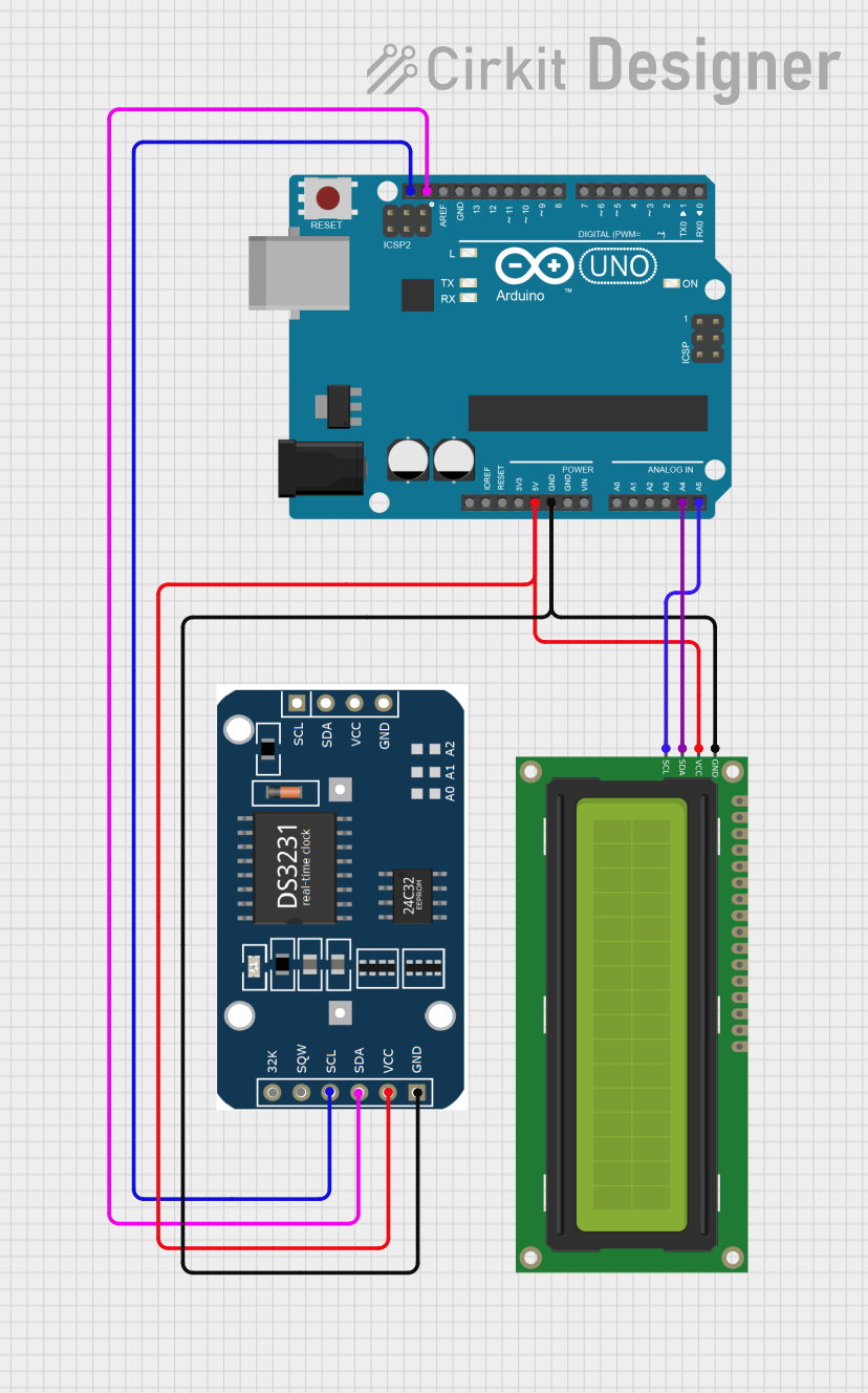
Wiring the LCD to an Arduino UNO
To use a 16x2 LCD with an Arduino UNO, follow these steps:
Connect the LCD pins to the Arduino as shown below:
- VSS → GND
- VDD → 5V
- V0 → Middle pin of a 10kΩ potentiometer (other two pins to 5V and GND)
- RS → Arduino digital pin 12
- RW → GND
- E → Arduino digital pin 11
- D4-D7 → Arduino digital pins 5, 4, 3, 2 (for 4-bit mode)
- LED+ → 5V (via a 220Ω resistor)
- LED- → GND
Install the LiquidCrystal library in the Arduino IDE (pre-installed in most cases).
Use the following example code to display text on the LCD:
#include <LiquidCrystal.h>

// Initialize the library with the numbers of the interface pins
LiquidCrystal lcd(12, 11, 5, 4, 3, 2);

void setup() {
  lcd.begin(16, 2); // Set up the LCD's number of columns and rows
  lcd.print("Hello, World!"); // Print a message to the LCD
}

void loop() {
  lcd.setCursor(0, 1); // Move the cursor to the second row
  lcd.print("LCD Tutorial!"); // Display text on the second row
  delay(1000); // Wait for 1 second
  lcd.clear(); // Clear the display
  lcd.print("Learn & Build!"); // Display new text
  delay(1000); // Wait for 1 second
}
Important Considerations
- Always use a potentiometer to adjust the contrast for optimal visibility.
- Use current-limiting resistors (e.g., 220Ω) for the backlight to prevent damage.
- Ensure proper grounding to avoid noise or flickering issues.
- For 4-bit mode, only connect pins D4-D7 to the microcontroller, leaving D0-D3 unconnected.
Troubleshooting and FAQs
Common Issues and Solutions
The LCD does not display anything:
- Check the power connections (VSS to GND, VDD to 5V).
- Adjust the contrast using the potentiometer connected to V0.
- Verify the wiring of the RS, RW, and E pins.
The text is garbled or incorrect:
- Ensure the data pins (D4-D7) are correctly connected to the microcontroller.
- Verify that the code matches the wiring configuration.
The backlight does not turn on:
- Check the LED+ and LED- connections.
- Ensure the current-limiting resistor is properly connected.
The display flickers or behaves erratically:
- Ensure a stable power supply.
- Check for loose or faulty connections.
FAQs
Q: Can I use the LCD in 8-bit mode?
A: Yes, you can use all eight data pins (D0-D7) for 8-bit mode. However, 4-bit mode is more common as it reduces the number of required connections.
Q: How do I display custom characters?
A: Use the createChar() function in the LiquidCrystal library to define and display custom characters.
Q: Can I use the LCD with a 3.3V microcontroller?
A: Most 16x2 LCDs require 5V for proper operation. Use a level shifter or a 5V power source for compatibility.
By following this guide, you can successfully integrate an LCD into your projects and troubleshoot common issues effectively. Happy building!