
How to Use HCMS-291x/297x 8-Character Serial LED Display: Examples, Pinouts, and Specs
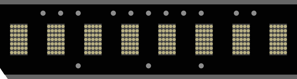
 Design with HCMS-291x/297x 8-Character Serial LED Display in Cirkit Designer
Introduction
The HCMS-291x/297x is a compact, serially interfaced LED display module manufactured by Broadcom. It is capable of displaying up to 8 alphanumeric characters, making it ideal for applications requiring clear and concise text output in a small form factor. This module integrates LED characters, drivers, and a shift register into a single package, simplifying design and reducing component count.
Explore Projects Built with HCMS-291x/297x 8-Character Serial LED Display
 Open Project in Cirkit Designer
 Open Project in Cirkit Designer
 Open Project in Cirkit Designer
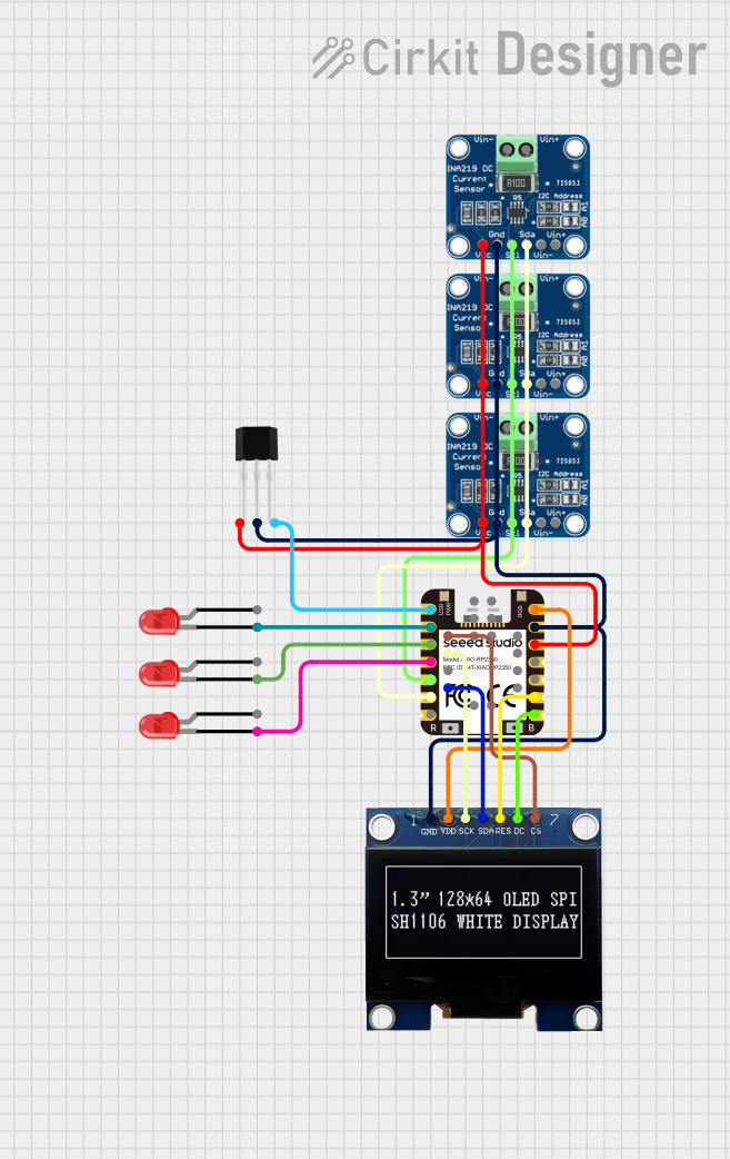 Open Project in Cirkit Designer
Explore Projects Built with HCMS-291x/297x 8-Character Serial LED Display
Open Project in Cirkit DesignerOpen Project in Cirkit DesignerOpen Project in Cirkit DesignerOpen Project in Cirkit DesignerCommon Applications and Use Cases
- Industrial control panels
- Consumer electronics
- Test and measurement equipment
- Communication devices
- Embedded systems requiring alphanumeric displays
Technical Specifications
The HCMS-291x/297x series offers a range of features and specifications that make it versatile for various applications. Below are the key technical details:
Key Specifications
| Parameter | Value |
|---|---|
| Display Type | 8-character alphanumeric LED display |
| Interface | Serial (SPI-compatible) |
| Operating Voltage (Vcc) | 4.5V to 5.5V |
| Typical Current Consumption | 15 mA per character (typical) |
| Character Set | ASCII (96 characters) |
| Operating Temperature Range | -40°C to +85°C |
| Dimensions | 20.1 mm x 5.0 mm x 3.0 mm (typical) |
Pin Configuration and Descriptions
The HCMS-291x/297x module has a 14-pin configuration. Below is the pinout and description:
| Pin Number | Pin Name | Description |
|---|---|---|
| 1 | Vcc | Positive power supply (4.5V to 5.5V) |
| 2 | GND | Ground |
| 3 | DATA IN | Serial data input |
| 4 | CLK | Clock input for serial data |
| 5 | LOAD/CS | Load or chip select signal |
| 6 | RESET | Resets the display module |
| 7 | DATA OUT | Serial data output for cascading modules |
| 8-14 | NC | No connection (reserved for internal use) |
Usage Instructions
The HCMS-291x/297x is designed for ease of use in embedded systems. Below are the steps and considerations for integrating this module into your circuit:
Connecting the Module
- Power Supply: Connect the Vcc pin to a 5V power source and the GND pin to ground.
- Serial Interface:
- Connect the
DATA INpin to the microcontroller's MOSI (Master Out Slave In) pin. - Connect the
CLKpin to the microcontroller's SPI clock pin. - Connect the
LOAD/CSpin to a GPIO pin configured as chip select.
- Connect the
- Reset: Connect the
RESETpin to a GPIO pin or tie it to Vcc for normal operation. - Cascading Modules: If using multiple modules, connect the
DATA OUTpin of the first module to theDATA INpin of the next module.
Example Code for Arduino UNO
Below is an example of how to interface the HCMS-291x/297x with an Arduino UNO:
#include <SPI.h>

// Pin definitions
#define LOAD_PIN 10  // Chip select pin
#define RESET_PIN 9  // Reset pin

void setup() {
  pinMode(LOAD_PIN, OUTPUT);
  pinMode(RESET_PIN, OUTPUT);

  // Initialize SPI
  SPI.begin();
  SPI.setClockDivider(SPI_CLOCK_DIV16); // Set SPI clock speed
  SPI.setDataMode(SPI_MODE0);           // Set SPI mode
  SPI.setBitOrder(MSBFIRST);            // Send most significant bit first

  // Reset the display
  digitalWrite(RESET_PIN, LOW);
  delay(10);
  digitalWrite(RESET_PIN, HIGH);

  // Initialize the display
  digitalWrite(LOAD_PIN, LOW);
  sendData(0x01); // Example command to clear the display
  digitalWrite(LOAD_PIN, HIGH);
}

void loop() {
  // Display "HELLO" on the module
  digitalWrite(LOAD_PIN, LOW);
  sendData(0x48); // ASCII for 'H'
  sendData(0x45); // ASCII for 'E'
  sendData(0x4C); // ASCII for 'L'
  sendData(0x4C); // ASCII for 'L'
  sendData(0x4F); // ASCII for 'O'
  digitalWrite(LOAD_PIN, HIGH);

  delay(1000); // Wait for 1 second
}

// Function to send data to the display
void sendData(byte data) {
  SPI.transfer(data);
}
Important Considerations
- Power Supply: Ensure a stable 5V power supply to avoid flickering or malfunction.
- Reset Signal: Always reset the module during initialization to ensure proper operation.
- SPI Configuration: Use SPI mode 0 and MSB-first data order for compatibility.
- Cascading: When cascading multiple modules, ensure proper data flow by connecting
DATA OUTtoDATA INof the next module.
Troubleshooting and FAQs
Common Issues
Display Not Working:
- Check the power supply connections (Vcc and GND).
- Verify the SPI connections and configuration.
- Ensure the
RESETpin is properly initialized.
Incorrect Characters Displayed:
- Verify the data being sent matches the ASCII character set.
- Check for timing issues in the SPI communication.
Flickering Display:
- Ensure the power supply can handle the current requirements.
- Check for loose connections or poor soldering.
Solutions and Tips
- Use decoupling capacitors (e.g., 0.1 µF) near the Vcc pin to stabilize the power supply.
- If cascading modules, ensure the clock and data signals are not degraded over long distances.
- Test the module with a simple program to verify functionality before integrating it into a complex system.
FAQs
Q: Can I use this module with a 3.3V microcontroller?
A: The HCMS-291x/297x requires a 5V power supply. Use level shifters for 3.3V microcontrollers.
Q: How many modules can I cascade?
A: The number of modules depends on the driving capability of your microcontroller and the SPI clock speed. Typically, up to 4-6 modules can be cascaded without significant signal degradation.
Q: Is the module compatible with I2C?
A: No, the HCMS-291x/297x uses an SPI-compatible serial interface.
This concludes the documentation for the HCMS-291x/297x 8-Character Serial LED Display.