How to Use GY-30 BH1750FVI : Examples, Pinouts, and Specs
Introduction
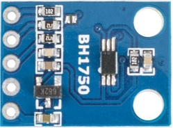
The GY-30 BH1750FVI is a digital light intensity sensor module that provides precise measurements of ambient light intensity. It incorporates the BH1750FVI IC, which is capable of detecting light intensity in a wide range and communicating the data through an I2C interface. This sensor is widely used in applications such as adjusting screen brightness in mobile devices, in home automation systems for controlling lighting, and in weather stations to monitor light conditions.
Explore Projects Built with GY-30 BH1750FVI

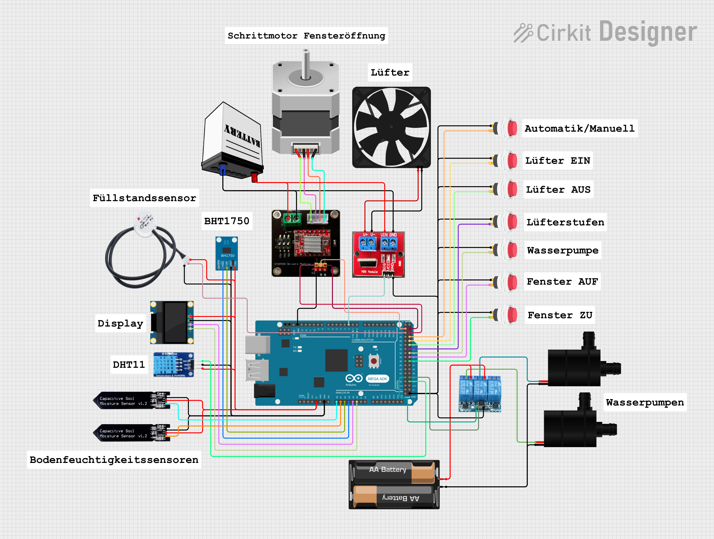

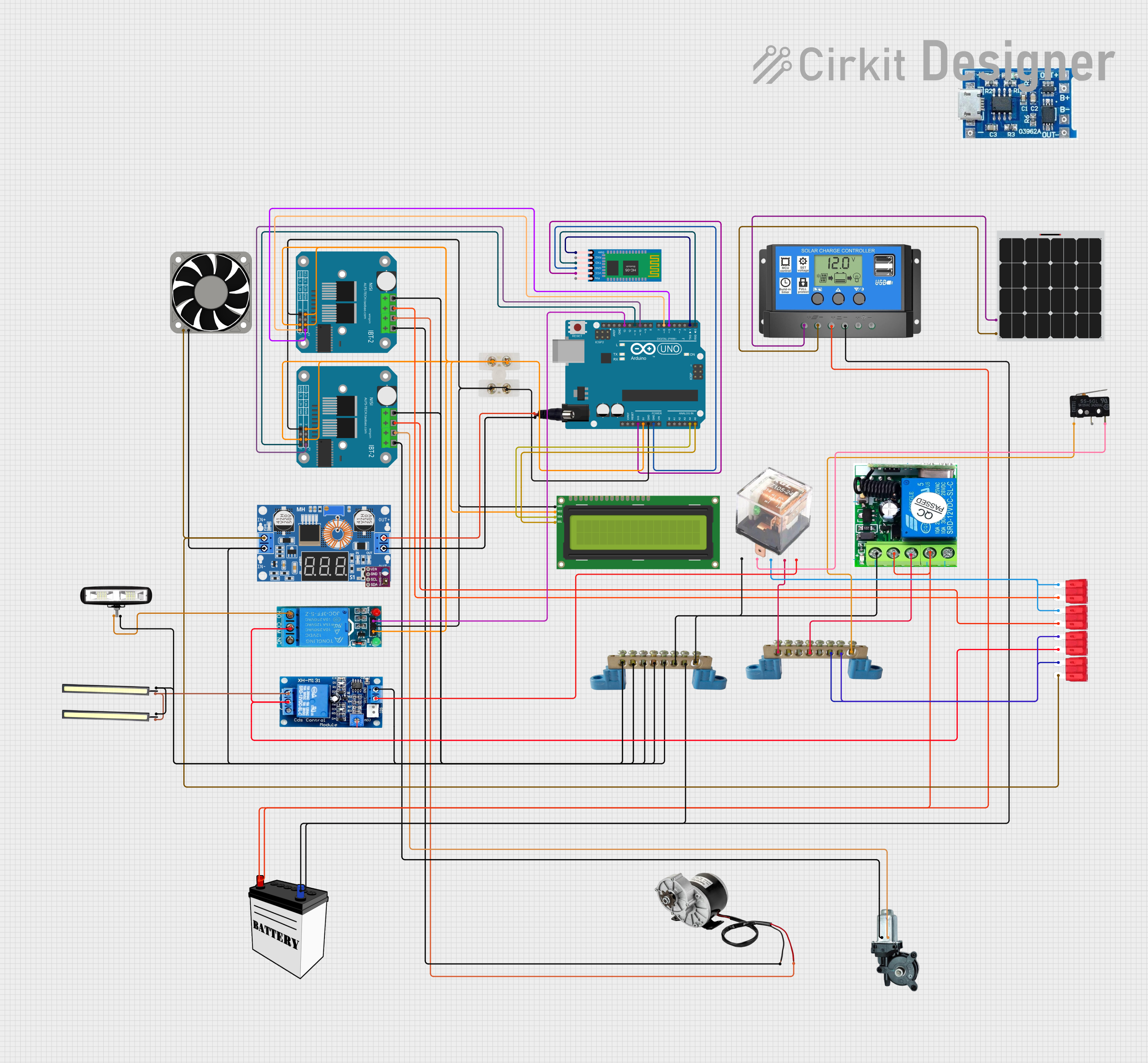
Explore Projects Built with GY-30 BH1750FVI
Common Applications and Use Cases
- Mobile devices for screen brightness control
- Home automation for controlling lighting based on ambient light
- Weather stations for recording light conditions
- Industrial lighting systems for maintaining consistent light levels
- Agricultural equipment to monitor sunlight for plants
Technical Specifications
Key Technical Details
- Operating Voltage: 2.4V to 3.6V
- Measurement Range: 1 to 65535 lx (Lux)
- Resolution: 1 lx (High-Resolution Mode)
- Communication: I2C interface
- I2C Address: 0x23 (ADDR pin grounded) or 0x5C (ADDR pin tied to VCC)
- Operating Temperature Range: -40°C to 85°C
Pin Configuration and Descriptions
| Pin Number | Pin Name | Description |
|---|---|---|
| 1 | VCC | Power supply (2.4V to 3.6V) |
| 2 | GND | Ground |
| 3 | SCL | Serial Clock Line for I2C communication |
| 4 | SDA | Serial Data Line for I2C communication |
| 5 | ADDR | Address selection pin |
Usage Instructions
How to Use the Component in a Circuit
- Connect the VCC pin to a 2.4V to 3.6V power supply.
- Connect the GND pin to the ground of the power supply.
- Connect the SCL and SDA pins to the I2C clock and data lines, respectively.
- If using the default I2C address (0x23), leave the ADDR pin unconnected. If you need to use the alternate address (0x5C), connect the ADDR pin to VCC.
Important Considerations and Best Practices
- Ensure that the power supply voltage does not exceed the maximum rating of 3.6V.
- Use pull-up resistors on the SCL and SDA lines, as required by the I2C protocol.
- Avoid exposing the sensor to direct sunlight or strong artificial light sources that could exceed its maximum measurement range.
- When integrating with microcontrollers like Arduino, ensure that the logic levels are compatible. Use a logic level converter if necessary.
Example Code for Arduino UNO
#include <Wire.h>
#include <BH1750.h>

BH1750 lightMeter;

void setup(){
  Wire.begin();
  Serial.begin(9600);

  lightMeter.begin(BH1750::CONTINUOUS_HIGH_RES_MODE);
  Serial.println(F("BH1750 Test"));
}

void loop() {
  uint16_t lux = lightMeter.readLightLevel();
  Serial.print("Light: ");
  Serial.print(lux);
  Serial.println(" lx");
  delay(1000);
}
Code Comments
#include <Wire.h>: Includes the Wire library for I2C communication.#include <BH1750.h>: Includes the BH1750 library to interface with the sensor.BH1750 lightMeter;: Creates an instance of the BH1750 class.Wire.begin();: Initializes the I2C communication.Serial.begin(9600);: Initializes serial communication at 9600 baud rate.lightMeter.begin(BH1750::CONTINUOUS_HIGH_RES_MODE);: Initializes the sensor in high-resolution mode.uint16_t lux = lightMeter.readLightLevel();: Reads the light level in lux.Serial.print("Light: ");: Prints the string "Light: " to the serial monitor.Serial.print(lux);: Prints the light level reading to the serial monitor.Serial.println(" lx");: Prints " lx" and a newline to the serial monitor.delay(1000);: Waits for 1000 milliseconds before the next reading.
Troubleshooting and FAQs
Common Issues Users Might Face
- Incorrect Readings: Ensure that the sensor is not exposed to direct light sources that exceed its range. Check for proper I2C communication and correct pull-up resistor values.
- No Data on Serial Monitor: Verify that the baud rate of the serial monitor matches the
Serial.begin()setting in your code. Check the wiring and connections. - Sensor Not Detected: Make sure that the sensor's I2C address matches the one used in your code. Check the ADDR pin connection.
Solutions and Tips for Troubleshooting
- Check Wiring: Double-check all connections, especially the I2C lines and power supply.
- Use Example Code: Start with the provided example code to ensure the sensor is working correctly.
- I2C Scanner: Use an I2C scanner sketch to verify that the sensor is detected on the I2C bus.
- Serial Debugging: Add serial print statements in your code to debug and track down where the issue might be occurring.
FAQs
Q: Can I use multiple BH1750 sensors on the same I2C bus? A: Yes, you can use multiple sensors by connecting the ADDR pin to different levels (GND or VCC) to change their I2C addresses.
Q: What is the maximum distance for the I2C lines? A: I2C is designed for short-distance communication. Keep the lines as short as possible, preferably within a few centimeters. If longer distances are required, consider using I2C bus extenders.
Q: How can I calibrate the sensor? A: The BH1750 sensor is factory-calibrated. However, if you need to adjust the readings, you can apply a software correction factor in your code.
Q: Is the sensor waterproof? A: No, the GY-30 BH1750FVI module is not waterproof. Protect it from moisture and water to prevent damage.