How to Use PowerBoost 500 Charger Pad: Examples, Pinouts, and Specs
Introduction
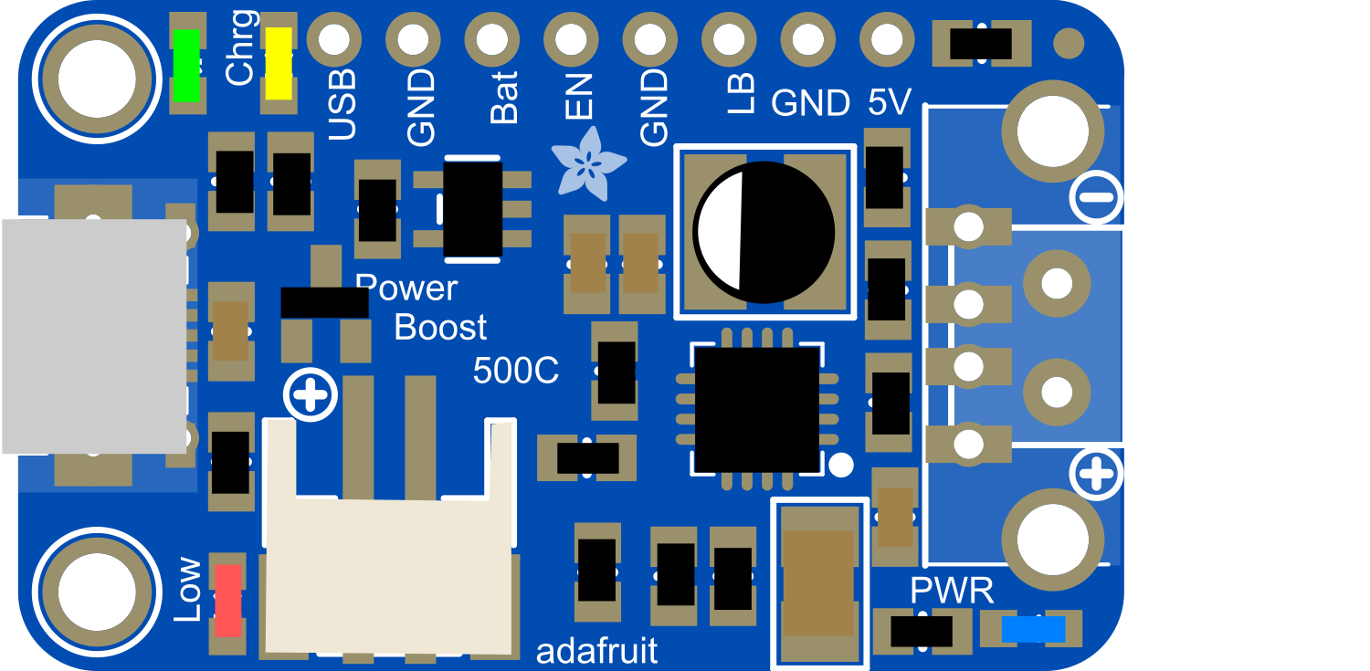
The PowerBoost 500 Charger Pad is a versatile and compact electronic component designed to provide a 5V power supply with a maximum output current of 500mA. This component integrates a power boost converter with a USB charging circuit, making it ideal for portable electronics, wearable devices, and DIY projects that require a stable power source from a lower voltage battery, such as a single-cell LiPo (Lithium Polymer) battery. The pad version is particularly suitable for embedding into custom PCB designs, offering a streamlined solution for power management.
Explore Projects Built with PowerBoost 500 Charger Pad


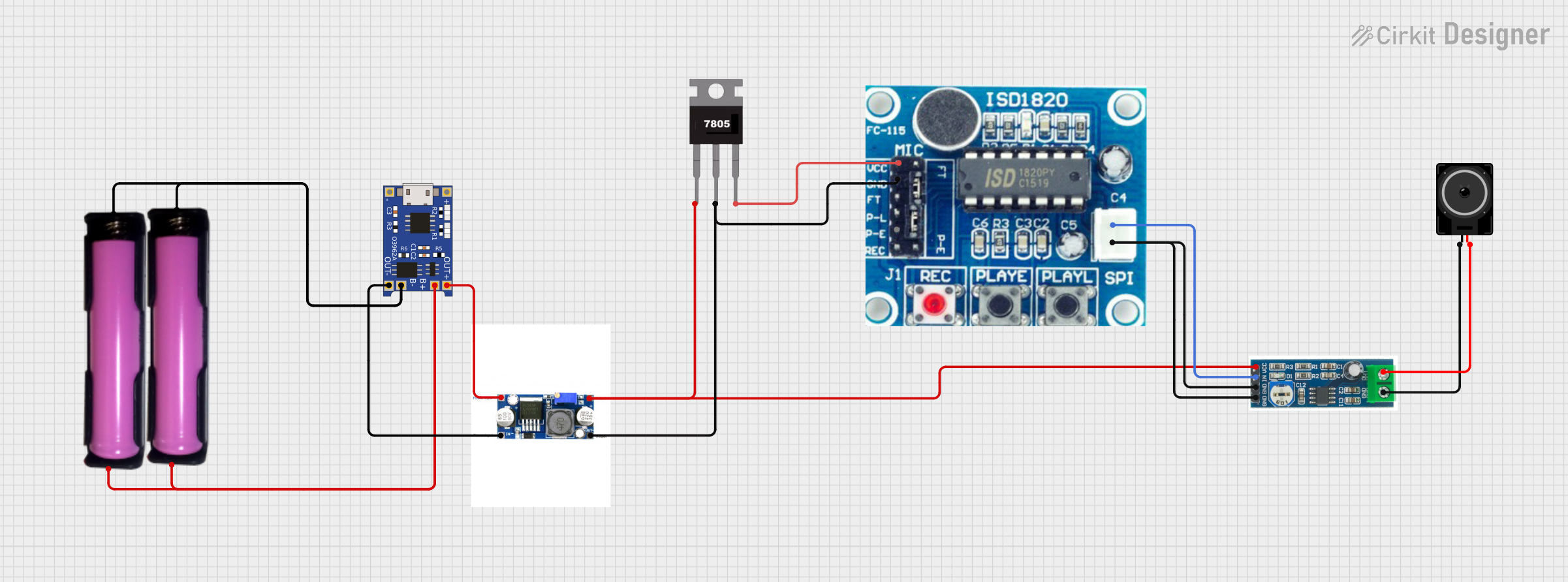
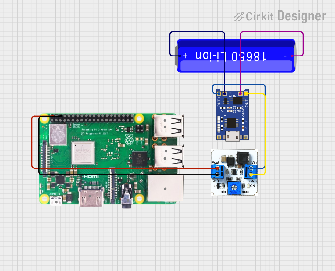
Explore Projects Built with PowerBoost 500 Charger Pad
Common Applications and Use Cases
- Portable USB chargers
- Battery-powered projects requiring a 5V supply
- Wearable electronics
- DIY electronics projects with space constraints
- Integration into custom PCB designs for compact and efficient power supply
Technical Specifications
Key Technical Details
- Input Voltage: 3.7V nominal (suitable for LiPo batteries)
- Output Voltage: 5V fixed
- Maximum Output Current: 500mA
- Efficiency: Up to 90% (varies based on input and output conditions)
- Integrated charging circuit for USB devices
- Low battery indicator output
Pin Configuration and Descriptions
| Pin Number | Name | Description |
|---|---|---|
| 1 | GND | Ground connection for both input and output. |
| 2 | BAT | Battery input, connect to the positive terminal of the battery. |
| 3 | 5V | Regulated 5V output, can supply up to 500mA. |
| 4 | EN | Enable pin, drive high to enable the boost converter. |
| 5 | LBO | Low Battery Output, goes low when the battery voltage is below a threshold. |
Usage Instructions
How to Use the Component in a Circuit
- Connect the positive terminal of a charged LiPo battery to the
BATpin. - Connect the ground of the battery to the
GNDpin. - The
5Vpin will now output a regulated 5V when theENpin is driven high. - To enable the power boost converter, connect the
ENpin to a high logic level (e.g., 3.3V or 5V). To disable the converter, connect it to ground. - The
LBOpin can be connected to an LED or a microcontroller input pin to monitor the battery status.
Important Considerations and Best Practices
- Ensure that the battery used is capable of supplying the required current for your application.
- Avoid placing high-power components too close to the PowerBoost 500 Charger Pad to prevent heat buildup.
- When integrating into a PCB, provide adequate copper area for heat dissipation.
- Do not exceed the maximum input and output ratings to prevent damage to the component.
Troubleshooting and FAQs
Common Issues Users Might Face
- No Output Voltage: Ensure the
ENpin is driven high and the battery is properly charged and connected. - Insufficient Output Current: Check if the battery is capable of supplying the required current. Replace the battery if necessary.
- Overheating: Make sure there is enough space around the component for heat dissipation.
Solutions and Tips for Troubleshooting
- If the
LBOpin is active, recharge the battery to ensure proper operation. - Double-check all connections, especially the polarity of the battery.
- If the device is not functioning, disconnect the power and inspect the board for any signs of damage or soldering issues.
FAQs
Q: Can I use the PowerBoost 500 Charger Pad with batteries other than LiPo? A: The PowerBoost 500 Charger Pad is optimized for 3.7V LiPo batteries. Using other types of batteries is not recommended and may not provide the desired performance.
Q: What should I do if the PowerBoost 500 Charger Pad is not boosting the voltage to 5V?
A: Verify that the EN pin is high and that the battery is properly charged. If the issue persists, inspect the component and connections for any faults.
Q: Is it possible to charge the battery through the PowerBoost 500 Charger Pad? A: Yes, the PowerBoost 500 Charger Pad includes a charging circuit for recharging the connected LiPo battery via a USB connection.
Q: How can I integrate the PowerBoost 500 Charger Pad into my custom PCB design? A: The pad version of the PowerBoost 500 Charger Pad is designed for easy integration. Refer to the manufacturer's footprint and layout guidelines when designing your PCB.
Q: Can I connect multiple devices to the 5V output? A: Yes, as long as the total current draw does not exceed 500mA.
Example Code for Arduino UNO
The following example demonstrates how to monitor the battery status using an Arduino UNO:
// Define the pin connected to the Low Battery Output (LBO)
const int lowBatteryPin = 2;

void setup() {
  // Set the lowBatteryPin as an input
  pinMode(lowBatteryPin, INPUT);

  // Begin serial communication at 9600 baud rate
  Serial.begin(9600);
}

void loop() {
  // Read the state of the low battery indicator
  int batteryStatus = digitalRead(lowBatteryPin);

  // If the LBO pin is LOW, the battery is below the threshold voltage
  if (batteryStatus == LOW) {
    Serial.println("Low battery warning!");
  } else {
    Serial.println("Battery level is OK.");
  }

  // Wait for 1 second before checking again
  delay(1000);
}
Remember to keep code comments concise and within the 80 character line length limit.