
How to Use Adafruit Feedback Servo (large): Examples, Pinouts, and Specs
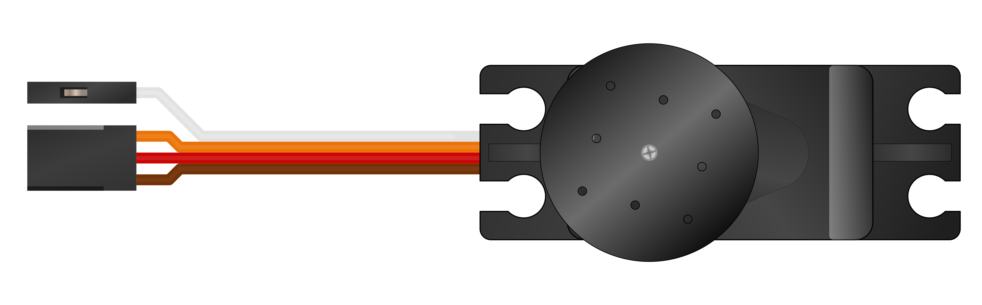
 Design with Adafruit Feedback Servo (large) in Cirkit Designer
Introduction
The Adafruit Feedback Servo (Large) (Manufacturer Part ID: 1404) is a high-torque servo motor with built-in feedback capabilities. This feature allows users to monitor the servo's position in real-time, enabling precise control of position and speed. It is ideal for applications requiring accurate motion control, such as robotics, automation systems, and animatronics.
Explore Projects Built with Adafruit Feedback Servo (large)
 Open Project in Cirkit Designer
 Open Project in Cirkit Designer
 Open Project in Cirkit Designer
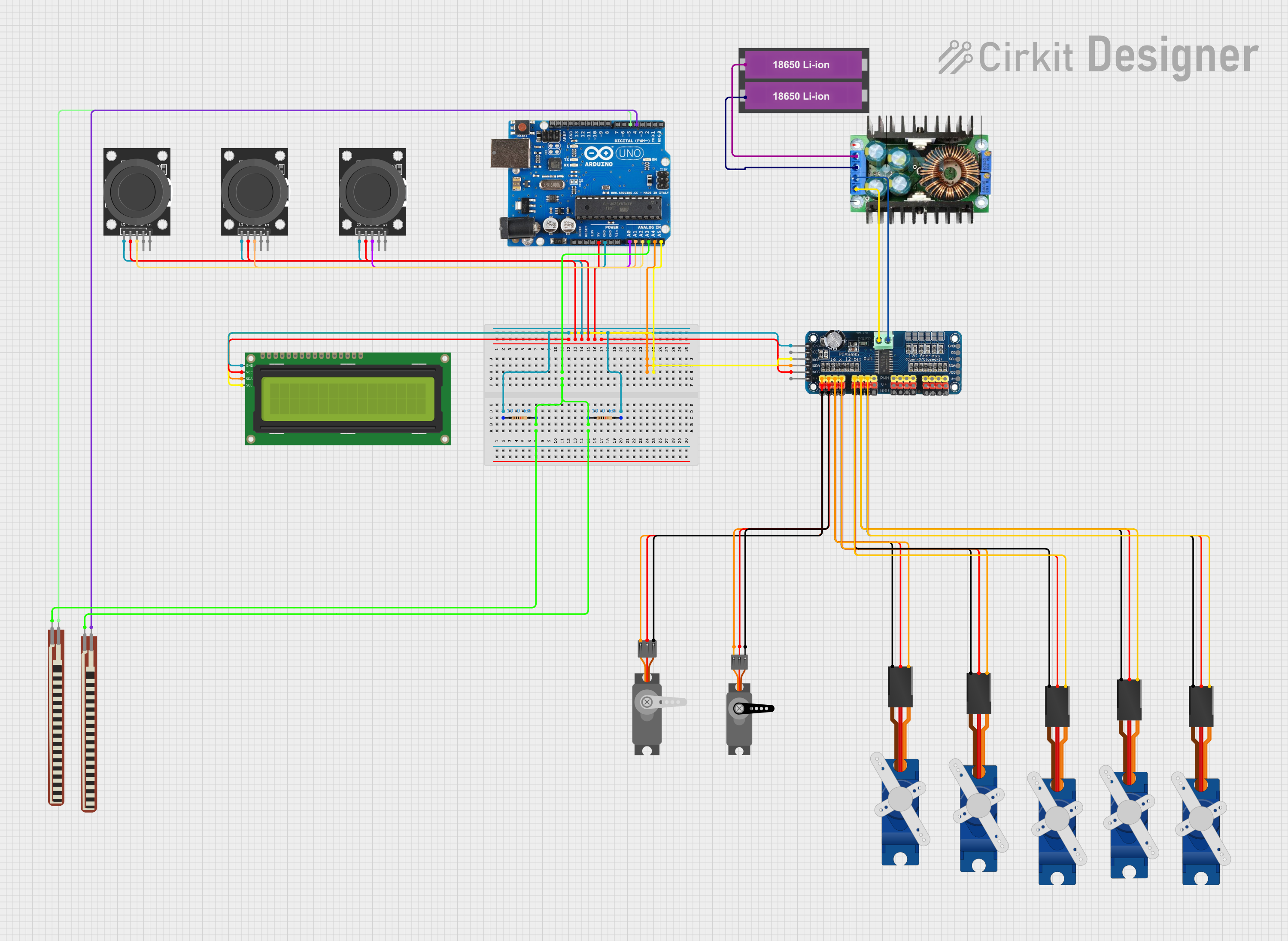 Open Project in Cirkit Designer
Explore Projects Built with Adafruit Feedback Servo (large)
Open Project in Cirkit DesignerOpen Project in Cirkit DesignerOpen Project in Cirkit DesignerOpen Project in Cirkit DesignerCommon Applications
- Robotics (e.g., robotic arms, grippers, and mobile robots)
- Automation systems
- Animatronics and motion control
- Educational projects involving servo control
- Projects requiring position feedback for closed-loop systems
Technical Specifications
Below are the key technical details for the Adafruit Feedback Servo (Large):
| Specification | Value |
|---|---|
| Operating Voltage | 4.8V to 6.0V |
| Stall Torque | 4.5 kg·cm (at 4.8V), 5.5 kg·cm (at 6.0V) |
| Operating Speed | 0.20 sec/60° (at 4.8V), 0.16 sec/60° (at 6.0V) |
| Feedback Type | Analog voltage proportional to position |
| Control Signal | PWM (Pulse Width Modulation) |
| PWM Pulse Range | 500 µs to 2500 µs |
| Dimensions | 40.8 mm x 20.1 mm x 38 mm |
| Weight | 41 g |
| Connector Type | 3-pin standard servo connector + feedback wire |
Pin Configuration
The Adafruit Feedback Servo has a standard 3-pin servo connector for control and power, along with an additional feedback wire. The pinout is as follows:
3-Pin Servo Connector
| Pin | Wire Color | Description |
|---|---|---|
| 1 | Brown | Ground (GND) |
| 2 | Red | Power (VCC) |
| 3 | Orange | PWM Signal Input |
Feedback Wire
| Wire Color | Description |
|---|---|
| Yellow | Analog feedback signal (position output) |
Usage Instructions
Connecting the Servo
- Power Supply: Connect the red wire to a 4.8V–6.0V power source. Ensure the power supply can provide sufficient current (at least 1A) to handle the servo's load.
- Ground: Connect the brown wire to the ground of your power supply and control system.
- PWM Signal: Connect the orange wire to a PWM-capable pin on your microcontroller (e.g., Arduino).
- Feedback Signal: Connect the yellow wire to an analog input pin on your microcontroller to read the servo's position.
Example Circuit with Arduino UNO
Below is an example of how to connect the Adafruit Feedback Servo to an Arduino UNO:
- Servo Power: Connect the red wire to the 5V pin on the Arduino.
- Ground: Connect the brown wire to the GND pin on the Arduino.
- PWM Signal: Connect the orange wire to digital pin 9 on the Arduino.
- Feedback Signal: Connect the yellow wire to analog pin A0 on the Arduino.
Example Arduino Code
The following Arduino code demonstrates how to control the servo and read its position feedback:
#include <Servo.h> // Include the Servo library

Servo myServo; // Create a Servo object
const int feedbackPin = A0; // Analog pin for feedback signal
const int servoPin = 9;     // PWM pin for servo control

void setup() {
  Serial.begin(9600); // Initialize serial communication
  myServo.attach(servoPin); // Attach the servo to the PWM pin
}

void loop() {
  // Move the servo to 0 degrees
  myServo.write(0);
  delay(1000); // Wait for the servo to reach the position

  // Read and print the feedback voltage
  int feedbackValue = analogRead(feedbackPin);
  float position = map(feedbackValue, 0, 1023, 0, 180); // Map feedback to degrees
  Serial.print("Servo Position: ");
  Serial.print(position);
  Serial.println(" degrees");

  // Move the servo to 90 degrees
  myServo.write(90);
  delay(1000);

  // Move the servo to 180 degrees
  myServo.write(180);
  delay(1000);
}
Important Considerations
- Power Supply: Use a dedicated power supply for the servo if it draws too much current for your microcontroller's onboard regulator.
- PWM Signal: Ensure the PWM signal is within the specified pulse range (500 µs to 2500 µs) to avoid damaging the servo.
- Feedback Signal: The feedback signal is an analog voltage proportional to the servo's position. Use an analog-to-digital converter (ADC) to read this signal.
Troubleshooting and FAQs
Common Issues
Servo Not Moving
- Cause: Insufficient power supply or incorrect wiring.
- Solution: Verify the power supply voltage and current. Check all connections.
Erratic Movement
- Cause: Noise in the PWM signal or insufficient power.
- Solution: Use a stable power source and ensure the PWM signal is clean.
Feedback Signal Not Working
- Cause: Incorrect connection to the feedback wire.
- Solution: Ensure the yellow wire is connected to an analog input pin and that the pin is properly configured.
Overheating
- Cause: Prolonged stall conditions or excessive load.
- Solution: Avoid stalling the servo for extended periods and reduce the load.
FAQs
Q: Can I use this servo with a Raspberry Pi?
A: Yes, but you will need a PWM driver (e.g., Adafruit PCA9685) since the Raspberry Pi's GPIO pins do not provide hardware PWM suitable for servos.
Q: What is the purpose of the feedback wire?
A: The feedback wire provides an analog voltage proportional to the servo's position, allowing for closed-loop control or position monitoring.
Q: Can I power the servo directly from the Arduino?
A: While possible for light loads, it is recommended to use an external power supply to avoid overloading the Arduino's voltage regulator.
Q: What is the maximum rotation angle of this servo?
A: The servo typically rotates 180°, but this may vary slightly depending on the PWM signal range.
This concludes the documentation for the Adafruit Feedback Servo (Large). For further assistance, refer to the Adafruit website or community forums.