How to Use Buck converter: Examples, Pinouts, and Specs
Introduction
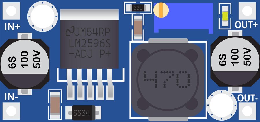
A Buck converter, also known as a step-down converter, is an essential electronic component used to convert a higher direct current (DC) input voltage to a lower DC output voltage with high efficiency. This type of power supply module is widely used in battery-operated devices, power supplies for various electronic applications, and as a voltage regulator in many circuits.
Common applications include:
- Portable devices (e.g., smartphones, laptops)
- Power management in embedded systems
- Automotive electronics
- LED drivers
- Renewable energy systems, such as solar power converters
Explore Projects Built with Buck converter


Explore Projects Built with Buck converter
Technical Specifications
Key Technical Details
- Input Voltage Range: Typically ranges from a couple of volts above the desired output to tens of volts.
- Output Voltage Range: Adjustable based on the design, often from 1V to several tens of volts.
- Efficiency: Up to 95%, depending on the design and load conditions.
- Switching Frequency: Varies with design, commonly from 100 kHz to several MHz.
- Load Current: Depending on the model, can range from a few milliamps to tens of amps.
Pin Configuration and Descriptions
| Pin Number | Name | Description |
|---|---|---|
| 1 | VIN | Input voltage supply pin. Connect to the source of the DC voltage to be stepped down. |
| 2 | GND | Ground pin. Connect to the system ground. |
| 3 | VOUT | Output voltage pin. This is where the buck converter provides the stepped-down voltage. |
| 4 | EN | Enable pin. A logic high signal here enables the buck converter, while a logic low signal disables it. |
| 5 | FB | Feedback pin. Used for voltage feedback to regulate the output voltage. Often connected to a voltage divider. |
Usage Instructions
How to Use the Buck Converter in a Circuit
- Connection: Connect the input voltage source to the VIN and GND pins. Ensure that the input voltage does not exceed the maximum rating of the buck converter.
- Output Voltage Setting: If the buck converter has an adjustable output, set the desired voltage using the feedback pin (FB) and an appropriate voltage divider or potentiometer.
- Enable the Converter: Apply a logic high signal to the EN pin to turn on the buck converter.
- Load Connection: Connect the load to the VOUT and GND pins.
Important Considerations and Best Practices
- Input Capacitor: Place a capacitor close to the VIN and GND pins to stabilize the input supply and reduce voltage spikes.
- Output Capacitor: Use an output capacitor to smooth out the voltage ripple and provide a stable output.
- Thermal Management: Ensure adequate cooling for the buck converter, especially at high load currents, to prevent overheating.
- Inductor Selection: Choose an inductor with a current rating above the maximum load current and low series resistance to maintain efficiency.
- Switching Noise: Be aware of potential electromagnetic interference (EMI) generated by the switching action. Proper layout and filtering can mitigate this.
Troubleshooting and FAQs
Common Issues
- Output Voltage Too Low or High: Check the feedback network and ensure the correct setting if the output is adjustable.
- Converter Not Starting: Verify the input voltage is within range and the EN pin is receiving a high signal.
- Overheating: Reduce the load current, improve cooling, or check for short circuits.
Solutions and Tips for Troubleshooting
- No Output: Ensure that the buck converter is enabled and that all connections are secure.
- Inconsistent Output: Check for proper capacitor and inductor values, and replace if necessary.
- Noise Issues: Add filtering capacitors or inductors, and keep the switching paths as short as possible.
FAQs
Q: Can I use a buck converter to charge batteries? A: Yes, but ensure that the output voltage is appropriate for the battery and that proper charging circuitry is in place.
Q: How do I choose the right inductor for my application? A: Consider the maximum load current, desired ripple current, and switching frequency. The inductor should have a saturation current above the peak load current.
Q: What is the purpose of the feedback pin? A: The feedback pin allows the buck converter to regulate the output voltage by comparing it to a reference voltage.
Example Code for Arduino UNO
Below is an example code snippet for controlling an Arduino-compatible buck converter module with an enable pin.
// Define the enable pin for the buck converter
const int buckConverterEnablePin = 7;

void setup() {
  // Set the enable pin as an output
  pinMode(buckConverterEnablePin, OUTPUT);
}

void loop() {
  // Enable the buck converter
  digitalWrite(buckConverterEnablePin, HIGH);
  delay(5000); // Keep the converter on for 5 seconds

  // Disable the buck converter
  digitalWrite(buckConverterEnablePin, LOW);
  delay(5000); // Keep the converter off for 5 seconds
}
This code will toggle the buck converter on and off every 5 seconds. Ensure that the enable pin on the buck converter is connected to pin 7 on the Arduino UNO.