How to Use 24V 4WD Electric Brushed DC Motor Controller : Examples, Pinouts, and Specs
Introduction
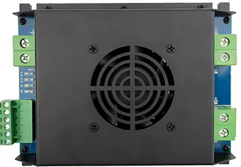
The 24V 4WD Electric Brushed DC Motor Controller (Manufacturer: L-faster, Part ID: Part 4) is a versatile device designed to regulate the speed and direction of 24V brushed DC motors. It is specifically tailored for four-wheel drive (4WD) applications, making it ideal for robotics, electric vehicles, and other motorized systems requiring precise control.
This motor controller enables efficient operation by providing smooth acceleration, deceleration, and directional control. It is robust and reliable, making it suitable for both hobbyist and industrial applications.
Explore Projects Built with 24V 4WD Electric Brushed DC Motor Controller
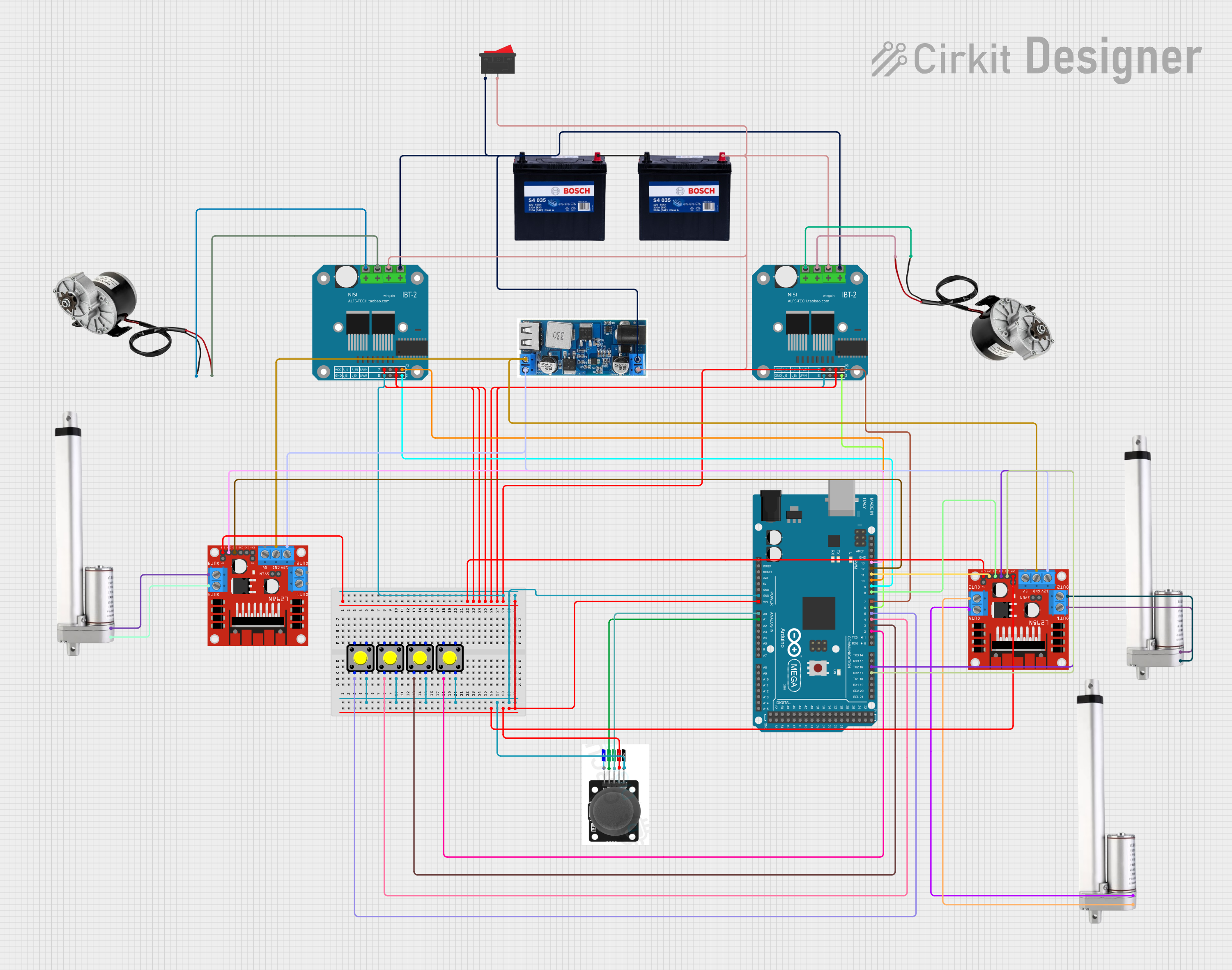


Explore Projects Built with 24V 4WD Electric Brushed DC Motor Controller
Common Applications
- Robotic vehicles and platforms
- Electric scooters and bicycles
- Remote-controlled cars and trucks
- Automated guided vehicles (AGVs)
- DIY motorized projects
Technical Specifications
Key Technical Details
| Parameter | Specification |
|---|---|
| Input Voltage | 24V DC |
| Maximum Current | 30A |
| Motor Type Supported | Brushed DC Motor |
| Control Signal Input | PWM (Pulse Width Modulation) |
| Direction Control | Forward/Reverse |
| Operating Temperature | -10°C to 50°C |
| Dimensions | 100mm x 70mm x 30mm |
| Weight | 150g |
Pin Configuration and Descriptions
The motor controller has several input and output connections. Below is the pin configuration:
Power and Motor Connections
| Pin Name | Description |
|---|---|
+24V |
Positive power input (24V DC) |
GND |
Ground connection for power input |
M+ |
Positive terminal for motor connection |
M- |
Negative terminal for motor connection |
Control Signal Connections
| Pin Name | Description |
|---|---|
PWM |
PWM signal input for speed control |
DIR |
Direction control input (High: Forward, Low: Reverse) |
EN |
Enable pin (High: Enable, Low: Disable) |
Usage Instructions
How to Use the Component in a Circuit
- Power Connection: Connect a 24V DC power supply to the
+24VandGNDpins of the motor controller. - Motor Connection: Attach the brushed DC motor to the
M+andM-terminals. - Control Signal Input:
- Use a microcontroller (e.g., Arduino UNO) to generate a PWM signal for speed control.
- Connect the PWM signal to the
PWMpin. - Use a digital output pin to control the
DIRpin for motor direction. - Optionally, use another digital output pin to control the
ENpin for enabling/disabling the motor.
- Testing: Power on the system and test the motor's speed and direction by varying the PWM signal and toggling the
DIRpin.
Important Considerations and Best Practices
- Ensure the power supply voltage does not exceed 24V to avoid damaging the controller.
- Use appropriate heat dissipation methods (e.g., heat sinks) if the motor operates at high currents for extended periods.
- Always connect the
GNDof the motor controller to theGNDof the microcontroller to ensure proper signal referencing. - Avoid sudden changes in direction at high speeds to prevent motor damage.
Example Arduino Code
Below is an example of how to control the motor controller using an Arduino UNO:
// Define pin connections
const int pwmPin = 9;  // PWM signal pin
const int dirPin = 8;  // Direction control pin
const int enPin = 7;   // Enable pin

void setup() {
  // Set pin modes
  pinMode(pwmPin, OUTPUT);
  pinMode(dirPin, OUTPUT);
  pinMode(enPin, OUTPUT);

  // Initialize motor controller
  digitalWrite(enPin, HIGH);  // Enable the motor controller
  digitalWrite(dirPin, LOW);  // Set initial direction to reverse
}

void loop() {
  // Example: Gradually increase motor speed
  for (int speed = 0; speed <= 255; speed++) {
    analogWrite(pwmPin, speed);  // Set motor speed (0-255)
    delay(20);                   // Wait for 20ms
  }

  // Change direction
  digitalWrite(dirPin, HIGH);  // Set direction to forward
  delay(1000);                 // Wait for 1 second

  // Gradually decrease motor speed
  for (int speed = 255; speed >= 0; speed--) {
    analogWrite(pwmPin, speed);  // Set motor speed (0-255)
    delay(20);                   // Wait for 20ms
  }

  // Disable motor for 2 seconds
  digitalWrite(enPin, LOW);  // Disable the motor controller
  delay(2000);               // Wait for 2 seconds
}
Troubleshooting and FAQs
Common Issues and Solutions
Motor Does Not Run:
- Ensure the power supply is properly connected and providing 24V DC.
- Verify that the
ENpin is set to HIGH to enable the motor controller. - Check the motor connections (
M+andM-) for loose or incorrect wiring.
Motor Runs in the Wrong Direction:
- Check the logic level of the
DIRpin. Set it to HIGH for forward and LOW for reverse. - Verify the motor wiring polarity.
- Check the logic level of the
Motor Speed is Not Adjustable:
- Ensure the PWM signal is being correctly generated by the microcontroller.
- Verify that the
PWMpin is properly connected to the microcontroller's PWM output.
Overheating:
- Ensure the motor is not drawing more current than the controller's maximum rating (30A).
- Use a heat sink or cooling fan to dissipate heat during prolonged operation.
FAQs
Q: Can I use this controller with a 12V motor?
A: No, this controller is specifically designed for 24V brushed DC motors. Using it with a 12V motor may result in suboptimal performance or damage.
Q: What is the maximum PWM frequency supported?
A: The controller supports PWM frequencies up to 20 kHz.
Q: Can I control multiple motors with this controller?
A: No, this controller is designed to control a single brushed DC motor. For multiple motors, use additional controllers.
Q: Is reverse braking supported?
A: No, this controller does not support active braking. It only provides forward and reverse direction control.
This concludes the documentation for the 24V 4WD Electric Brushed DC Motor Controller. For further assistance, refer to the manufacturer's support resources.