How to Use LED ROPE LIGHT (12V): Examples, Pinouts, and Specs
Introduction
LED rope lights are flexible linear lighting solutions that consist of small Light Emitting Diodes (LEDs) encased in a PVC jacket to form a long, continuous strip. They are designed to be easily bent, cut, and shaped, making them ideal for decorative lighting, accent lighting, and even task lighting in various applications. Common uses include lighting for architectural outlines, landscape illumination, signage, under-cabinet lighting, and holiday decorations.
Explore Projects Built with LED ROPE LIGHT (12V)
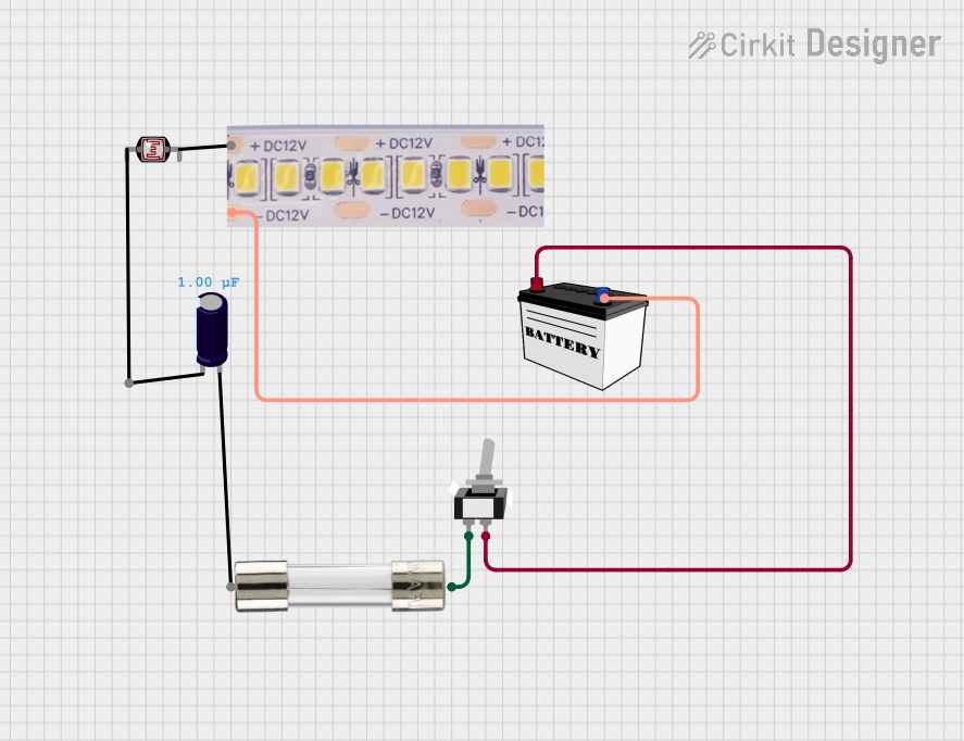
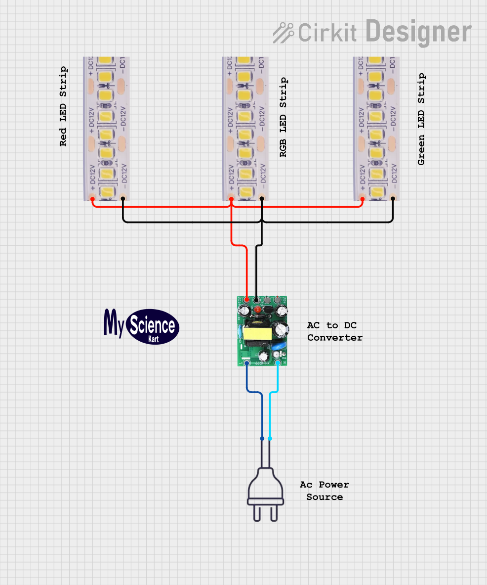
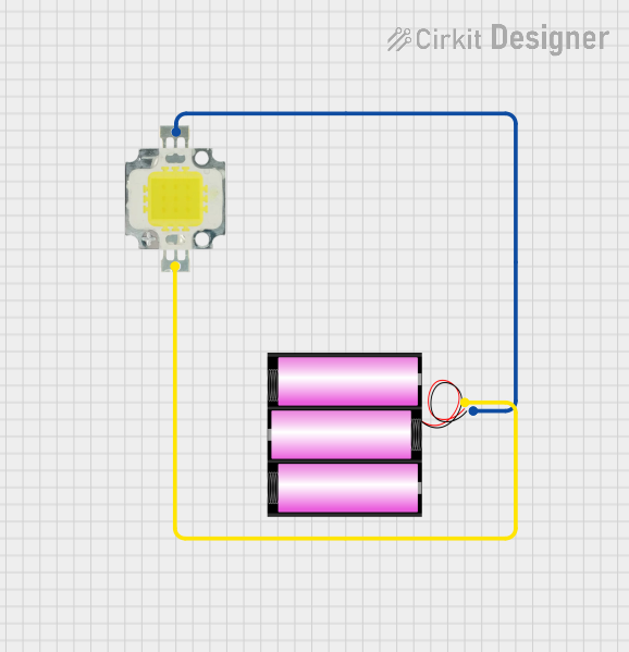
Explore Projects Built with LED ROPE LIGHT (12V)
Technical Specifications
Key Technical Details
- Voltage: 12V DC
- Power Consumption: Varies depending on length (typically measured in Watts per meter)
- LED Type: SMD (Surface Mounted Device)
- Color Temperature: Varies (e.g., Warm White, Cool White, RGB)
- Luminous Flux: Varies with LED density and color
- Beam Angle: 120 degrees
- Lifespan: Approximately 25,000 to 50,000 hours
- Operating Temperature: -20°C to 50°C
- Ingress Protection Rating: Varies (e.g., IP65 for water-resistant models)
Pin Configuration and Descriptions
Since LED rope lights are typically powered by a 12V DC source, they do not have a standard pin configuration like an integrated circuit. Instead, they have two or more wires for connection, depending on whether they are single-color or RGB. Below is a table for a single-color LED rope light:
| Wire Color | Description |
|---|---|
| Red | +12V DC Input |
| Black | Ground |
For RGB LED rope lights, the table might look like this:
| Wire Color | Description |
|---|---|
| Red | +12V DC Input |
| Green | Green Signal Wire |
| Blue | Blue Signal Wire |
| Black | Common Anode (Ground) |
Usage Instructions
How to Use the Component in a Circuit
- Power Supply: Ensure you have a 12V DC power supply that can provide sufficient current for the length of the LED rope light you are using.
- Connecting: Connect the red wire to the positive terminal of the power supply and the black wire to the negative terminal. For RGB models, additional connections for the green and blue signal wires are necessary.
- Mounting: Use the clips or adhesive backing (if provided) to mount the rope light to the desired surface. Ensure the surface is clean and dry before installation.
- Cutting: If customization of length is required, cut the rope light only at the marked intervals to ensure proper operation.
Important Considerations and Best Practices
- Do not exceed the maximum run length specified by the manufacturer, as voltage drop can cause dimming and uneven lighting.
- Avoid sharp bends that could damage the internal wiring of the rope light.
- Ensure proper insulation of any exposed wiring, especially if the rope light is cut to size.
- For outdoor applications, use rope lights with an appropriate IP rating to prevent water and dust ingress.
Troubleshooting and FAQs
Common Issues
- Dim or Uneven Lighting: This may be due to an excessive length of rope light for the power supply used. Check the power requirements and reduce the length or use a higher-rated power supply.
- Flickering Lights: Flickering can be caused by loose connections. Ensure all connections are secure and that the power supply is providing a stable voltage.
- Non-Functional Sections: If a section of the rope light is not working, it may have been damaged or cut incorrectly. Check for physical damage and ensure cuts were made at the designated intervals.
Solutions and Tips for Troubleshooting
- Double-check all connections for tightness and correct polarity.
- Measure the voltage at the beginning and end of the rope light to check for voltage drop.
- Replace any damaged sections or connectors as needed.
Example Arduino UNO Code for RGB LED Rope Light
// Define the control pins for the RGB LED rope light
const int redPin = 9;   // Red signal wire
const int greenPin = 10; // Green signal wire
const int bluePin = 11;  // Blue signal wire

void setup() {
  // Set the RGB LED pins as outputs
  pinMode(redPin, OUTPUT);
  pinMode(greenPin, OUTPUT);
  pinMode(bluePin, OUTPUT);
}

void loop() {
  // Set the color to red
  analogWrite(redPin, 255);   // Red at full brightness
  analogWrite(greenPin, 0);   // Green off
  analogWrite(bluePin, 0);    // Blue off
  delay(1000);                // Wait for 1 second

  // Set the color to green
  analogWrite(redPin, 0);     // Red off
  analogWrite(greenPin, 255); // Green at full brightness
  analogWrite(bluePin, 0);    // Blue off
  delay(1000);                // Wait for 1 second

  // Set the color to blue
  analogWrite(redPin, 0);     // Red off
  analogWrite(greenPin, 0);   // Green off
  analogWrite(bluePin, 255);  // Blue at full brightness
  delay(1000);                // Wait for 1 second
}
Note: The above code assumes the use of a common anode RGB LED rope light. If using a common cathode type, the logic will need to be inverted. Always ensure that the Arduino's output pins can handle the current required by the rope light or use appropriate drivers/transistors.