How to Use 16-Channel PWM Servo Driver: Examples, Pinouts, and Specs
Introduction
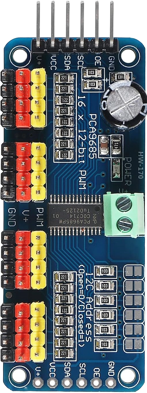
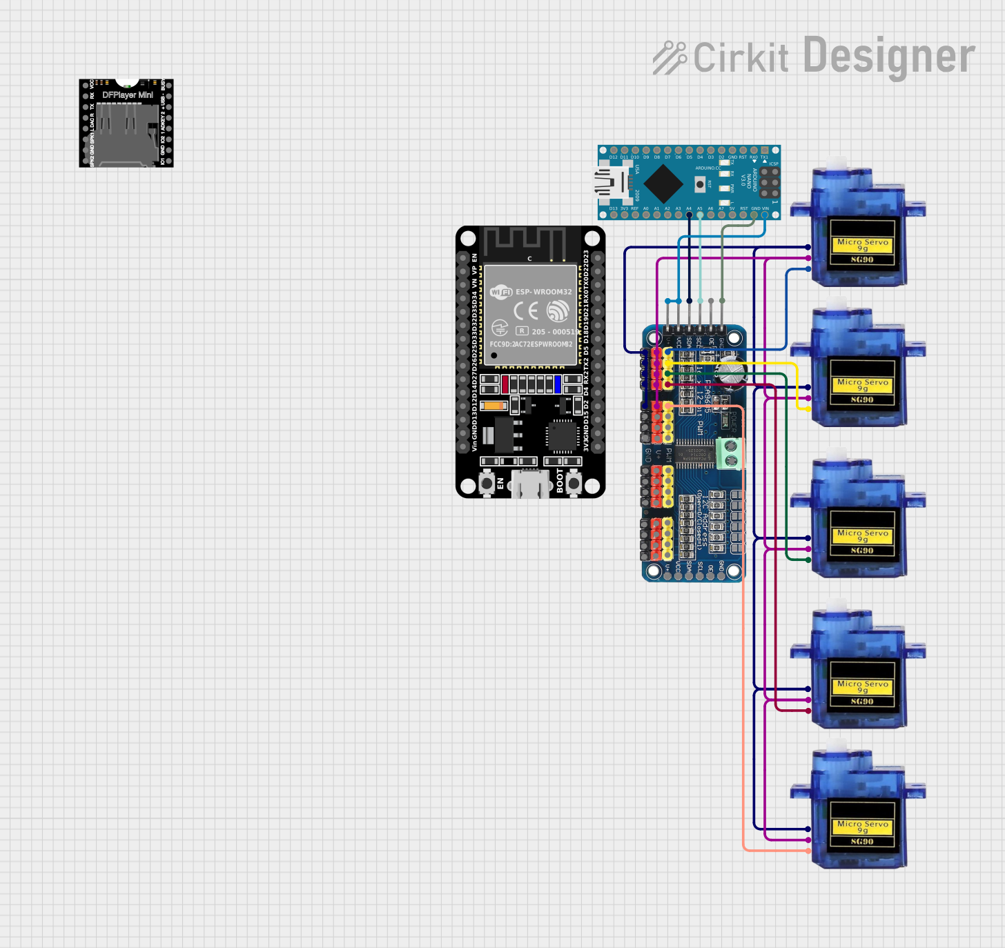
The 16-Channel PWM Servo Driver is a versatile device designed to control up to 16 servos or PWM outputs simultaneously. It uses pulse-width modulation (PWM) signals to provide precise control over the position and speed of each servo, making it an essential component in robotics, automation, and other applications requiring multi-servo control. This driver is typically controlled via I2C communication, making it compatible with microcontrollers like Arduino, Raspberry Pi, and others.
Explore Projects Built with 16-Channel PWM Servo Driver
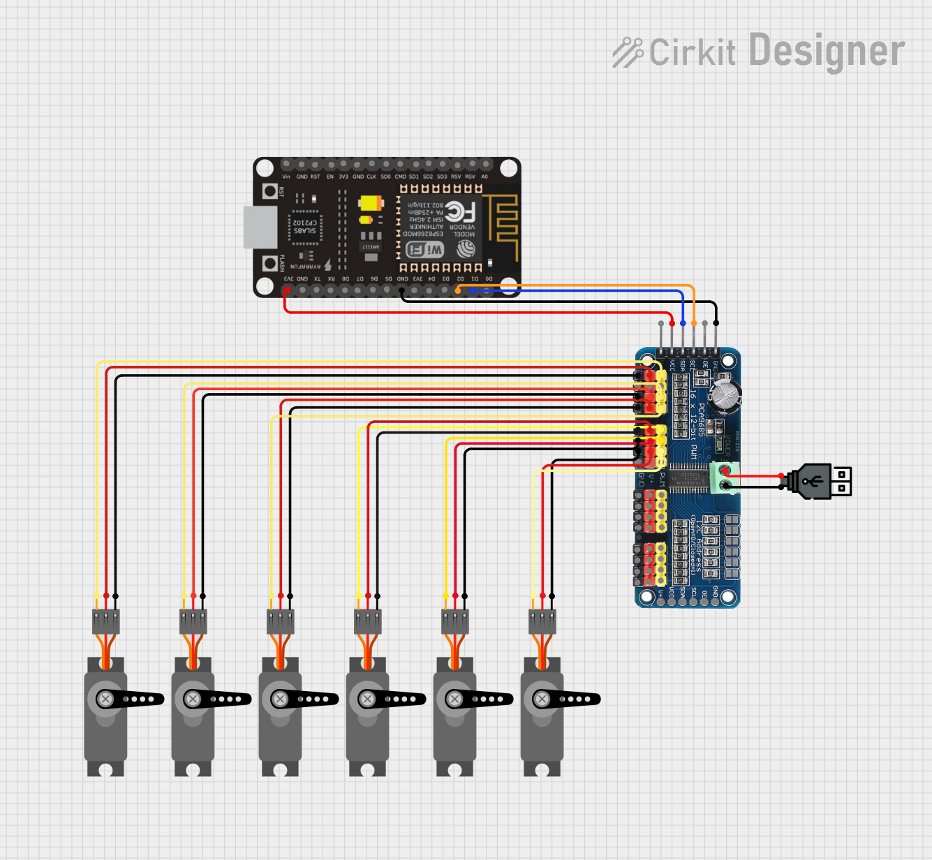
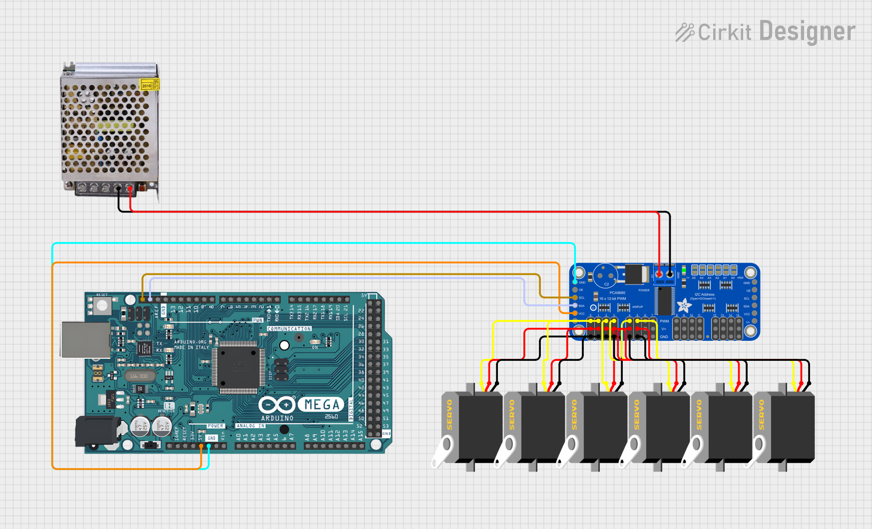
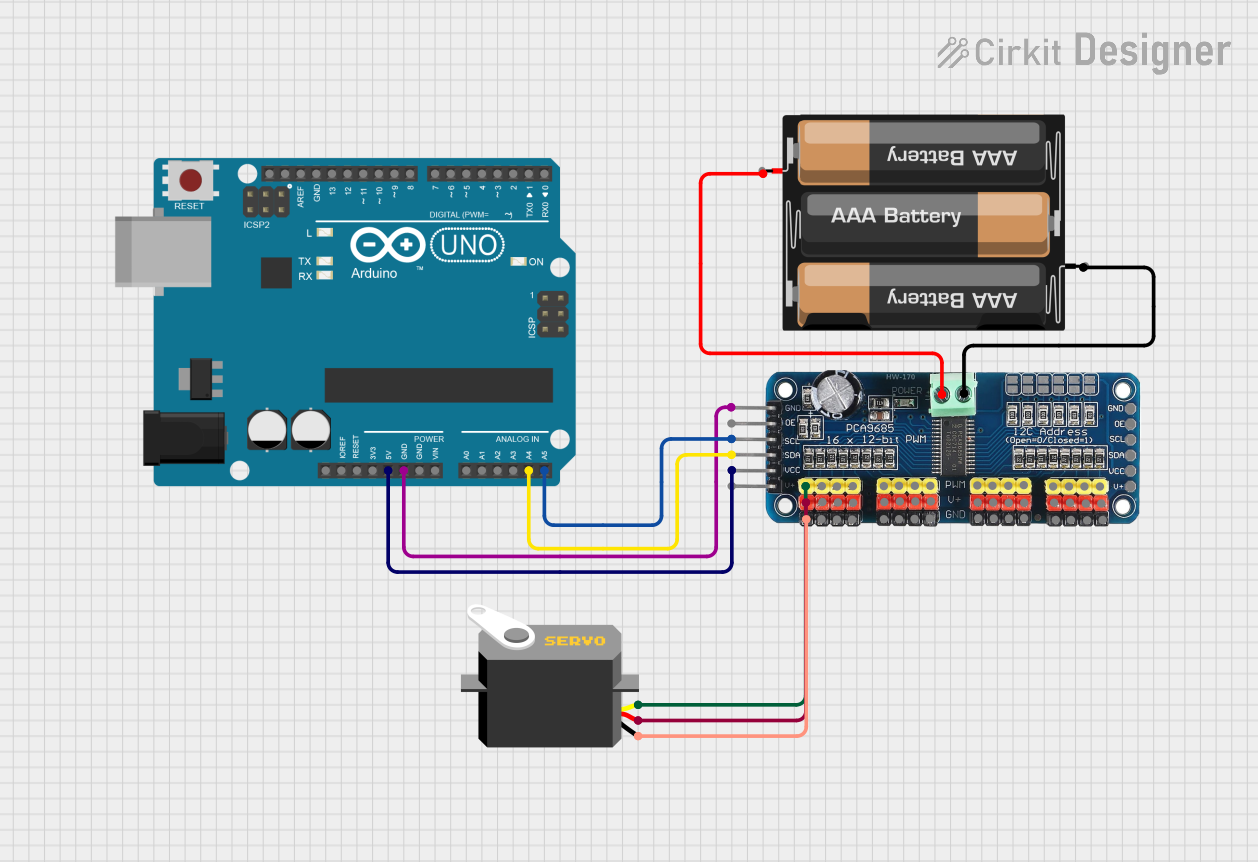
Explore Projects Built with 16-Channel PWM Servo Driver
Common Applications and Use Cases
- Robotics: Controlling robotic arms, legs, or grippers.
- Automation: Managing actuators in industrial systems.
- Animatronics: Driving multiple servos for lifelike motion.
- Model building: Controlling servos in RC cars, planes, or boats.
- LED control: Driving PWM-based LEDs for dimming or effects.
Technical Specifications
- Operating Voltage: 3.3V to 5.5V
- PWM Frequency: Adjustable from 40Hz to 1000Hz
- Resolution: 12-bit (4096 steps per PWM cycle)
- Communication Protocol: I2C (7-bit address, configurable)
- Output Channels: 16 independent PWM outputs
- Output Current: Up to 25mA per channel
- I2C Address Range: 0x40 to 0x7F (configurable via address pins)
- Dimensions: Typically 60mm x 25mm (varies by manufacturer)
Pin Configuration and Descriptions
| Pin Name | Description |
|---|---|
| VCC | Power input for the logic circuit (3.3V to 5.5V). |
| GND | Ground connection. |
| SDA | I2C data line for communication with the microcontroller. |
| SCL | I2C clock line for communication with the microcontroller. |
| OE | Output enable pin (active low). Disables all outputs when pulled high. |
| PWM 0-15 | 16 PWM output pins for connecting servos or other PWM-controlled devices. |
| A0-A5 | Address selection pins for configuring the I2C address of the device. |
Usage Instructions
How to Use the Component in a Circuit
- Power the Driver: Connect the VCC pin to a 3.3V or 5V power source and the GND pin to ground.
- Connect the I2C Lines: Connect the SDA and SCL pins to the corresponding I2C pins on your microcontroller.
- Set the I2C Address: Use the A0-A5 pins to configure the I2C address if multiple drivers are used.
- Connect Servos: Attach the servo signal wires to the PWM output pins (PWM 0-15). Ensure the servos are powered by an external power source capable of handling their current requirements.
- Enable Outputs: Ensure the OE pin is pulled low to enable the PWM outputs.
Important Considerations and Best Practices
- Power Supply: Use a separate power supply for the servos to avoid overloading the microcontroller's power regulator.
- Bypass Capacitors: Add a capacitor (e.g., 1000µF) across the servo power supply to stabilize voltage during operation.
- I2C Pull-Up Resistors: Ensure proper pull-up resistors (typically 4.7kΩ) are present on the SDA and SCL lines.
- PWM Frequency: Set the PWM frequency to match the requirements of your servos (typically 50Hz for standard servos).
- Avoid Overloading: Do not exceed the current rating of the driver or the power supply.
Example Code for Arduino UNO
Below is an example of how to control a servo using the 16-Channel PWM Servo Driver with an Arduino UNO:
#include <Wire.h>
#include <Adafruit_PWMServoDriver.h>

// Create an instance of the PWM driver
Adafruit_PWMServoDriver pwm = Adafruit_PWMServoDriver();

#define SERVOMIN 150 // Minimum pulse length count (adjust for your servo)
#define SERVOMAX 600 // Maximum pulse length count (adjust for your servo)

void setup() {
  Serial.begin(9600);
  Serial.println("16-Channel PWM Servo Driver Test");

  pwm.begin();                // Initialize the PWM driver
  pwm.setPWMFreq(50);         // Set PWM frequency to 50Hz for standard servos
}

void loop() {
  // Sweep servo on channel 0 from minimum to maximum position
  for (int pulse = SERVOMIN; pulse <= SERVOMAX; pulse++) {
    pwm.setPWM(0, 0, pulse);  // Set PWM signal on channel 0
    delay(10);                // Small delay for smooth motion
  }

  // Sweep servo back from maximum to minimum position
  for (int pulse = SERVOMAX; pulse >= SERVOMIN; pulse--) {
    pwm.setPWM(0, 0, pulse);  // Set PWM signal on channel 0
    delay(10);                // Small delay for smooth motion
  }
}
Troubleshooting and FAQs
Common Issues and Solutions
Servos Not Moving:
- Ensure the servos are powered by an adequate external power supply.
- Verify the I2C connections (SDA and SCL) and ensure pull-up resistors are present.
- Check the I2C address of the driver and ensure it matches the address in your code.
Erratic Servo Movement:
- Confirm that the PWM frequency is set correctly (e.g., 50Hz for standard servos).
- Add a bypass capacitor across the servo power supply to reduce noise.
Driver Not Responding:
- Check the wiring of the VCC and GND pins.
- Verify that the OE pin is pulled low to enable outputs.
- Use an I2C scanner sketch to confirm the driver is detected on the I2C bus.
Overheating:
- Ensure the current draw of the connected servos does not exceed the driver's or power supply's limits.
- Use a heat sink or active cooling if necessary.
FAQs
Can I use this driver with a Raspberry Pi? Yes, the driver is compatible with Raspberry Pi via the I2C interface. Use libraries like
Adafruit_Python_PCA9685for easy integration.What is the maximum number of drivers I can use simultaneously? Up to 62 drivers can be chained together by configuring unique I2C addresses using the A0-A5 pins.
Can I control LEDs with this driver? Yes, the driver can control PWM-based LEDs for dimming or effects. Adjust the PWM frequency as needed for LED applications.
What happens if I exceed the current rating? Exceeding the current rating may damage the driver or cause erratic behavior. Always ensure the total current draw is within safe limits.