How to Use BC547: Examples, Pinouts, and Specs
Introduction
The BC547 is a general-purpose NPN bipolar junction transistor (BJT) widely used in low-power amplification and switching applications. It is a reliable and versatile component, making it a popular choice for hobbyists and professionals alike. With a maximum collector current of 100 mA and a maximum voltage rating of 45 V, the BC547 is suitable for a variety of electronic circuits, including signal amplification, small motor control, and digital switching.
Explore Projects Built with BC547
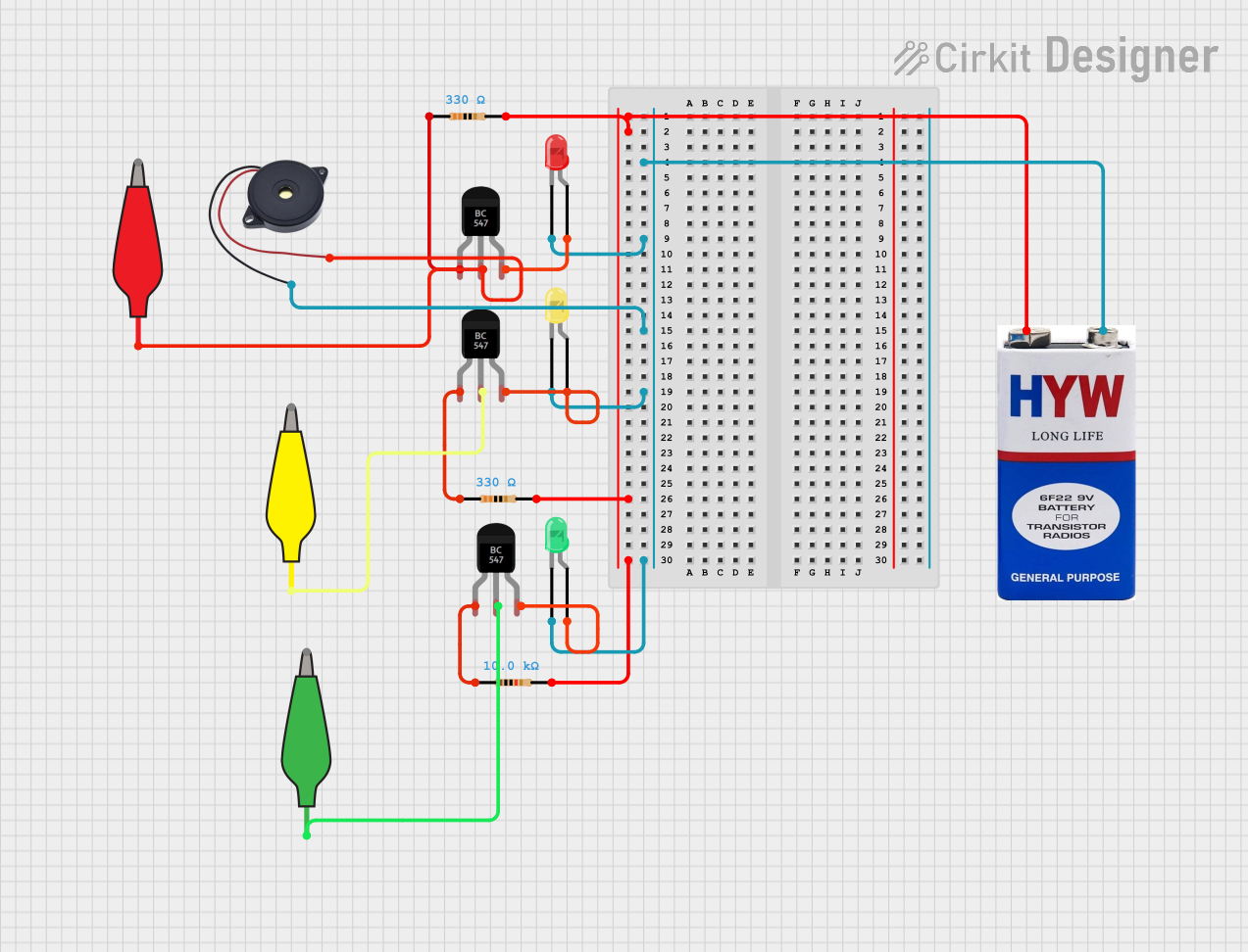
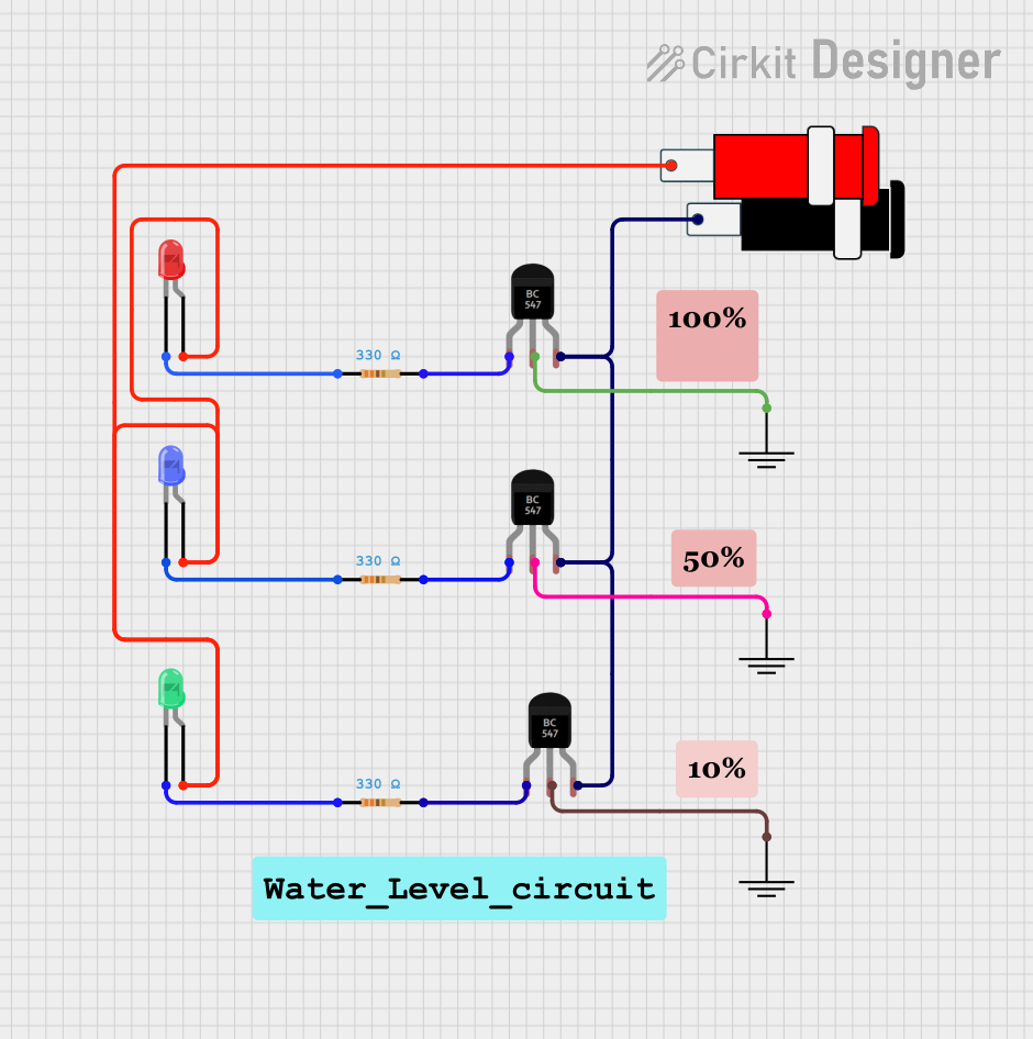
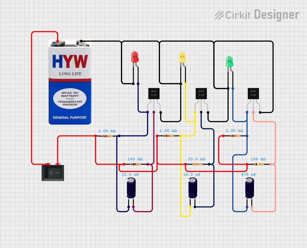
Explore Projects Built with BC547
Common Applications
- Signal amplification in audio and RF circuits
- Switching small loads such as LEDs or relays
- Oscillator circuits
- Voltage regulation and current limiting
- General-purpose low-power applications
Technical Specifications
Below are the key technical details of the BC547 transistor:
| Parameter | Value |
|---|---|
| Transistor Type | NPN |
| Maximum Collector Current (Ic) | 100 mA |
| Maximum Collector-Emitter Voltage (Vce) | 45 V |
| Maximum Collector-Base Voltage (Vcb) | 50 V |
| Maximum Emitter-Base Voltage (Veb) | 6 V |
| DC Current Gain (hFE) | 110 to 800 (varies by model) |
| Power Dissipation (Ptot) | 500 mW |
| Transition Frequency (ft) | 150 MHz |
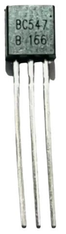
| Package Type | TO-92 |
Pin Configuration
The BC547 transistor comes in a TO-92 package with three pins. The pinout is as follows:
| Pin Number | Pin Name | Description |
|---|---|---|
| 1 | Collector | Current flows out of this pin. |
| 2 | Base | Controls the transistor's operation. |
| 3 | Emitter | Current flows into this pin. |
The pinout diagram for the BC547 (TO-92 package) is shown below:
   _______
  |       |
  |       |
  |_______|
   | | |
   1 2 3
   C B E
Usage Instructions
Using the BC547 in a Circuit
The BC547 transistor can be used in two primary configurations:
- Switching Mode: The transistor acts as an electronic switch, turning a load (e.g., an LED or relay) on or off.
- Amplification Mode: The transistor amplifies a small input signal to produce a larger output signal.
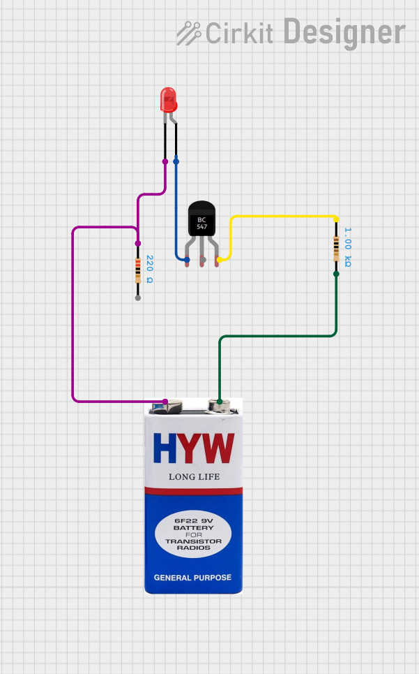
Example: Using BC547 as a Switch
Below is an example circuit where the BC547 is used to control an LED:
- Connect the collector to the positive terminal of the LED.
- Connect the emitter to the ground (GND).
- Use a resistor (e.g., 1 kΩ) between the base and the control signal (e.g., from an Arduino or microcontroller).
- Apply a small current to the base to turn the LED on.
Arduino Example Code
Here is an example of how to use the BC547 with an Arduino UNO to control an LED:
// Define the pin connected to the BC547 base
const int transistorBasePin = 9; // Pin 9 is connected to the base of BC547
const int delayTime = 1000;      // Delay time in milliseconds

void setup() {
  pinMode(transistorBasePin, OUTPUT); // Set the pin as an output
}

void loop() {
  digitalWrite(transistorBasePin, HIGH); // Turn on the transistor (LED ON)
  delay(delayTime);                      // Wait for 1 second
  digitalWrite(transistorBasePin, LOW);  // Turn off the transistor (LED OFF)
  delay(delayTime);                      // Wait for 1 second
}
Important Considerations
- Always use a base resistor to limit the current flowing into the base pin. A typical value is 1 kΩ.
- Ensure the collector current (Ic) does not exceed 100 mA to avoid damaging the transistor.
- The BC547 is not suitable for high-power applications; use a power transistor for such cases.
- Observe the correct pin configuration to avoid improper connections.
Troubleshooting and FAQs
Common Issues
The transistor does not switch the load:
- Check if the base resistor is properly connected and of the correct value.
- Ensure the base current is sufficient to saturate the transistor (typically 1/10th of the collector current).
The transistor overheats:
- Verify that the collector current does not exceed 100 mA.
- Check for proper heat dissipation and ensure the power dissipation is within limits.
The circuit does not work as expected:
- Double-check the pin connections (Collector, Base, Emitter).
- Ensure the supply voltage and load are within the transistor's specifications.
FAQs
Q: Can the BC547 be used to drive a motor?
A: The BC547 can drive small motors with a current requirement below 100 mA. For larger motors, use a power transistor or MOSFET.
Q: What is the purpose of the base resistor?
A: The base resistor limits the current flowing into the base pin, preventing damage to the transistor and ensuring proper operation.
Q: Can the BC547 amplify audio signals?
A: Yes, the BC547 is commonly used in audio amplification circuits for low-power applications.
Q: What is the difference between BC547A, BC547B, and BC547C?
A: The difference lies in their DC current gain (hFE) ranges:
- BC547A: 110 to 220
- BC547B: 200 to 450
- BC547C: 420 to 800
By understanding these specifications and guidelines, you can effectively use the BC547 transistor in your electronic projects.