
How to Use Tilt sensor: Examples, Pinouts, and Specs
 Design with Tilt sensor in Cirkit Designer
Introduction
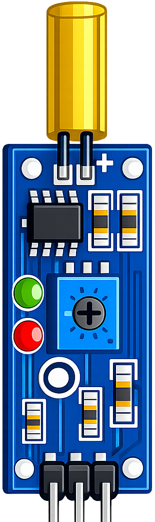
A tilt sensor is a device that detects the orientation or angle of an object relative to the ground. It typically uses a pendulum or a ball mechanism to sense changes in position. When the sensor is tilted beyond a certain threshold, it triggers a change in its output, which can be read by a microcontroller or other electronic systems. Tilt sensors are widely used in applications such as robotics, gaming, mobile devices, and industrial equipment to determine tilt angles or detect motion.
Explore Projects Built with Tilt sensor
 Open Project in Cirkit Designer
 Open Project in Cirkit Designer
 Open Project in Cirkit Designer
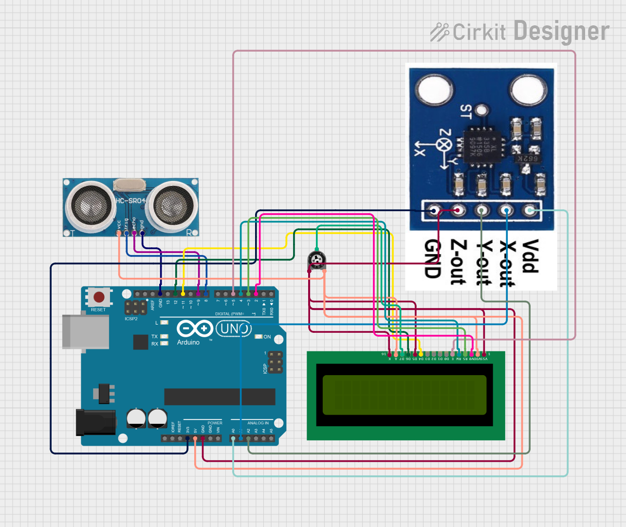 Open Project in Cirkit Designer
Explore Projects Built with Tilt sensor
Open Project in Cirkit DesignerOpen Project in Cirkit DesignerOpen Project in Cirkit DesignerOpen Project in Cirkit DesignerCommon Applications:
- Robotics: Detecting the orientation of robots or robotic arms.
- Gaming: Sensing motion or tilt in gaming controllers.
- Mobile Devices: Determining screen orientation (portrait/landscape).
- Industrial Equipment: Monitoring the tilt of machinery or vehicles for safety.
- Home Automation: Detecting the position of objects like doors or windows.
Technical Specifications
Below are the general technical specifications for a typical tilt sensor:
| Parameter | Value |
|---|---|
| Operating Voltage | 3.3V to 5V |
| Output Type | Digital (High/Low) |
| Response Time | < 10 ms |
| Operating Temperature | -10°C to 50°C |
| Dimensions | Varies (e.g., 10mm x 5mm x 5mm) |
| Mechanism | Ball or pendulum-based |
Pin Configuration
The tilt sensor typically has two pins. Below is the pin description:
| Pin | Name | Description |
|---|---|---|
| 1 | Signal (OUT) | Outputs a digital signal (HIGH or LOW) based on |
| the tilt state of the sensor. | ||
| 2 | Ground (GND) | Connects to the ground of the circuit. |
Usage Instructions
How to Use the Tilt Sensor in a Circuit
Connect the Pins:
- Connect the Signal (OUT) pin of the tilt sensor to a digital input pin on your microcontroller (e.g., Arduino).
- Connect the Ground (GND) pin to the ground of your circuit.
Power the Sensor:
- Ensure the sensor is powered with a voltage between 3.3V and 5V, depending on its specifications.
Read the Output:
- The sensor outputs a digital HIGH (1) when it is upright and a digital LOW (0) when tilted beyond its threshold angle.
Add a Pull-Down Resistor:
- If the sensor does not have an internal pull-down resistor, add an external resistor (e.g., 10kΩ) between the Signal pin and Ground to ensure stable readings.
Example: Connecting to an Arduino UNO
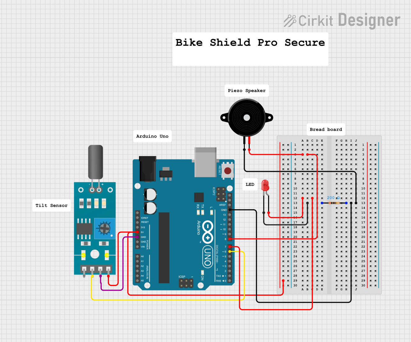
Below is an example of how to use a tilt sensor with an Arduino UNO:
Circuit Diagram:
- Signal (OUT) → Arduino Digital Pin 2
- GND → Arduino GND
Arduino Code:
// Tilt Sensor Example Code
// This code reads the state of the tilt sensor and prints the result to the Serial Monitor.

const int tiltSensorPin = 2; // Pin connected to the tilt sensor's Signal pin
int tiltState = 0;           // Variable to store the sensor's state

void setup() {
  pinMode(tiltSensorPin, INPUT); // Set the tilt sensor pin as input
  Serial.begin(9600);           // Initialize serial communication at 9600 baud
}

void loop() {
  tiltState = digitalRead(tiltSensorPin); // Read the tilt sensor's state

  if (tiltState == HIGH) {
    Serial.println("Sensor is upright!"); // Print message if sensor is upright
  } else {
    Serial.println("Sensor is tilted!");  // Print message if sensor is tilted
  }

  delay(500); // Wait for 500ms before reading again
}
Important Considerations:
- Orientation: Ensure the sensor is mounted in the correct orientation for accurate readings.
- Debouncing: The sensor may produce noisy signals when transitioning between states. Use software debouncing or a capacitor to smooth the output.
- Environmental Factors: Avoid using the sensor in environments with excessive vibration or extreme temperatures, as these can affect its performance.
Troubleshooting and FAQs
Common Issues and Solutions:
No Output Signal:
- Cause: Loose connections or incorrect wiring.
- Solution: Double-check all connections and ensure the sensor is properly powered.
Unstable Readings:
- Cause: Electrical noise or lack of a pull-down resistor.
- Solution: Add a pull-down resistor (e.g., 10kΩ) between the Signal pin and Ground.
Sensor Always Reads HIGH or LOW:
- Cause: Sensor may be damaged or mounted incorrectly.
- Solution: Verify the sensor's orientation and test with a multimeter to ensure it is functioning.
Slow Response:
- Cause: Excessive delay in the code or mechanical lag in the sensor.
- Solution: Reduce delays in the code and ensure the sensor is not obstructed.
FAQs:
Q1: Can I use the tilt sensor with a 3.3V microcontroller?
A1: Yes, most tilt sensors operate within a voltage range of 3.3V to 5V. Check the datasheet for your specific sensor to confirm compatibility.
Q2: How do I debounce the tilt sensor signal?
A2: You can use a small capacitor (e.g., 0.1µF) across the Signal pin and Ground to filter out noise. Alternatively, implement software debouncing in your code.
Q3: What is the maximum tilt angle the sensor can detect?
A3: The maximum tilt angle depends on the sensor's design. Most ball-based tilt sensors detect angles of approximately 15° to 45° from the upright position.
Q4: Can the tilt sensor detect continuous angles?
A4: No, basic tilt sensors only provide binary output (HIGH/LOW) and cannot measure continuous angles. For continuous angle measurement, consider using an accelerometer.
By following this documentation, you can effectively integrate a tilt sensor into your projects and troubleshoot common issues.