How to Use Arduino MKR WAN 1310: Examples, Pinouts, and Specs
Introduction
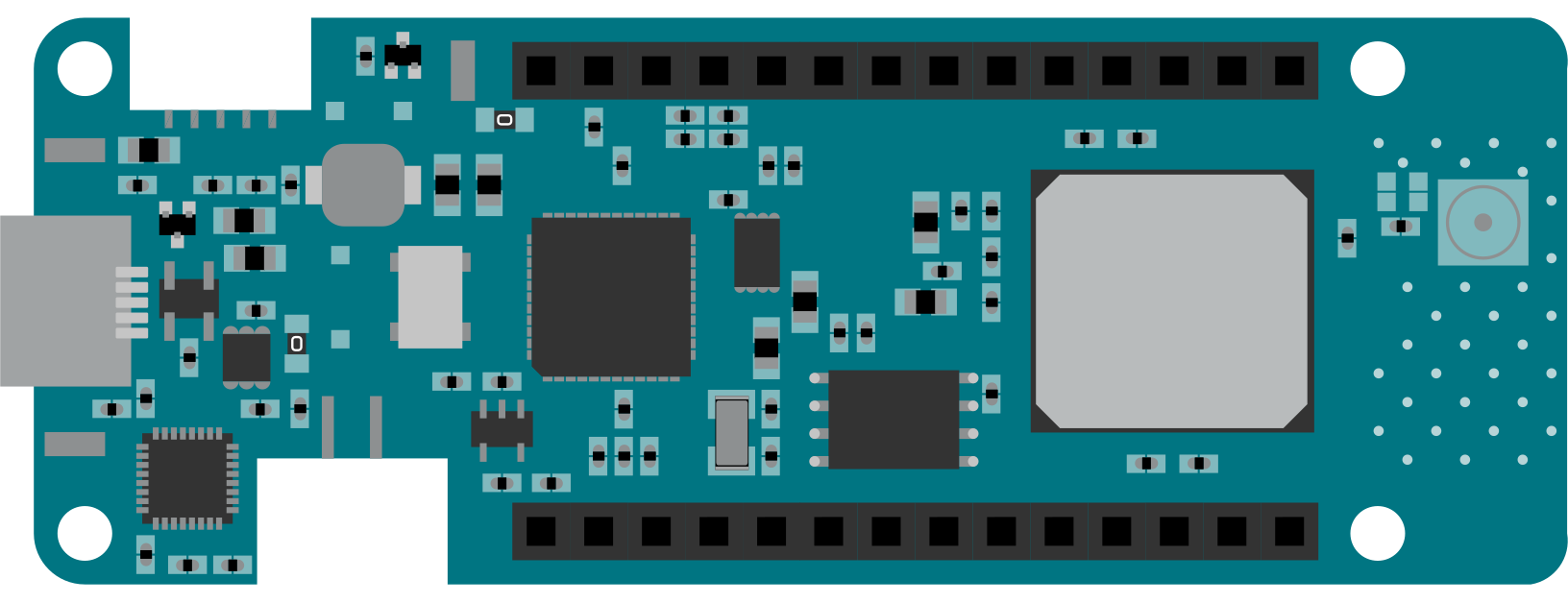
The Arduino MKR WAN 1310 is a microcontroller board specifically designed for Internet of Things (IoT) applications. It features LoRa connectivity, enabling long-range wireless communication, and is powered by the SAMD21 Cortex-M0+ 32-bit ARM microcontroller. Its compact form factor and low power consumption make it ideal for battery-powered projects and remote sensing applications.
Explore Projects Built with Arduino MKR WAN 1310
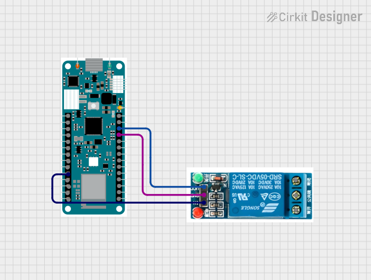
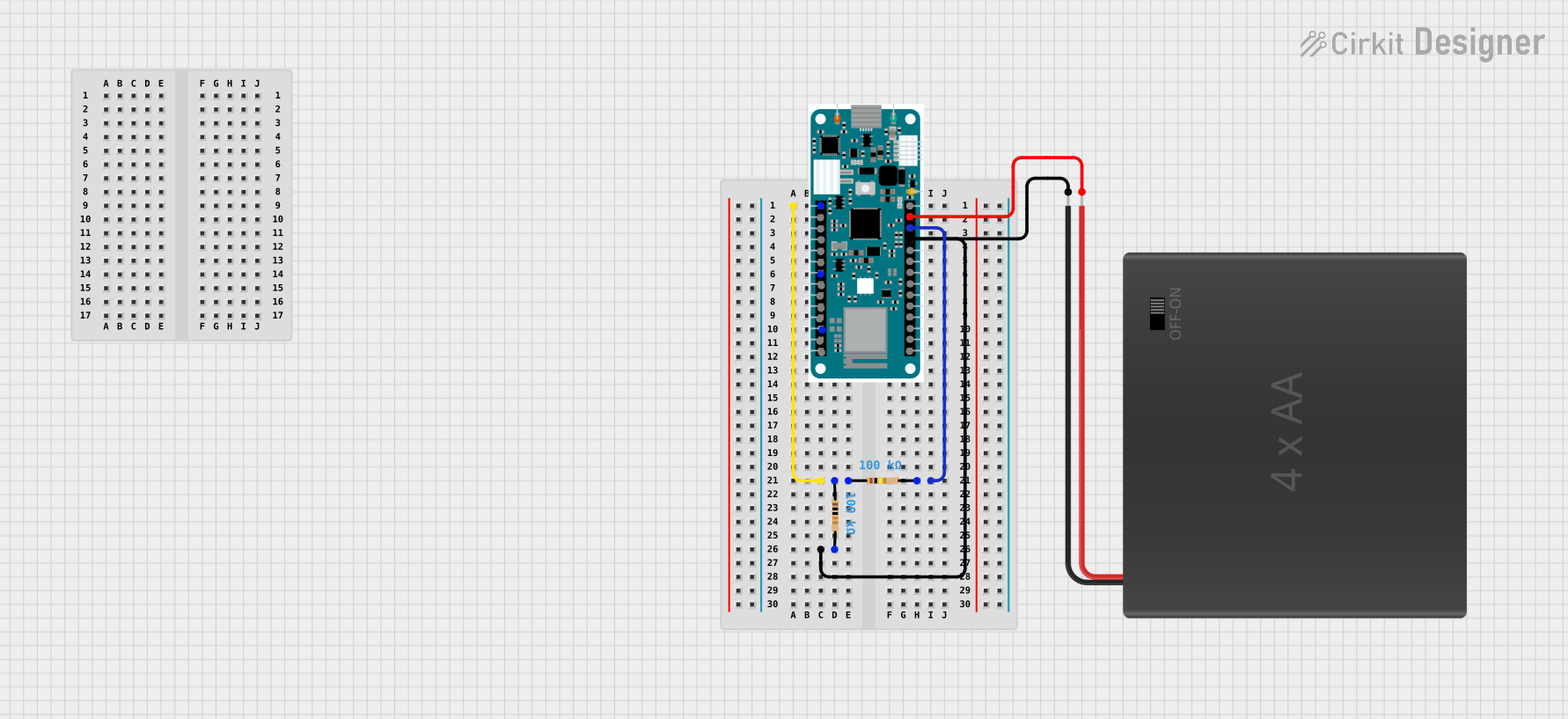
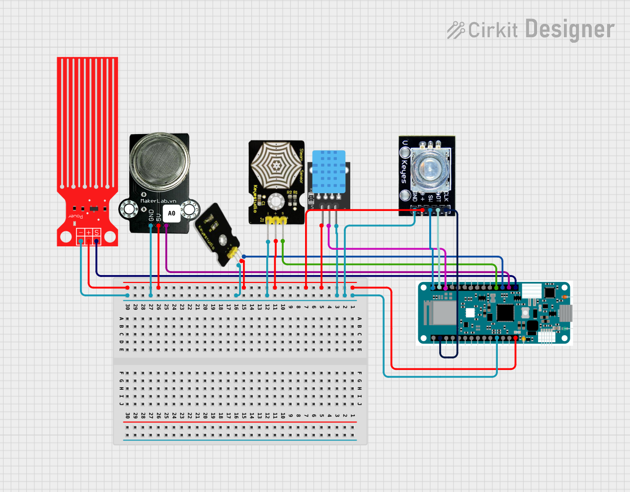
Explore Projects Built with Arduino MKR WAN 1310
Common Applications and Use Cases
- Smart agriculture and environmental monitoring
- Industrial IoT (IIoT) applications
- Asset tracking and geolocation
- Smart cities and infrastructure monitoring
- Home automation and remote control systems
Technical Specifications
Key Technical Details
| Specification | Value |
|---|---|
| Microcontroller | SAMD21 Cortex-M0+ 32-bit ARM |
| Operating Voltage | 3.3V |
| Input Voltage (via VIN) | 5V to 12V |
| Digital I/O Pins | 8 (of which 4 can be used as PWM outputs) |
| Analog Input Pins | 7 |
| Analog Output Pins | 1 (DAC) |
| Flash Memory | 256 KB |
| SRAM | 32 KB |
| Clock Speed | 48 MHz |
| Connectivity | LoRa (via Murata CMWX1ZZABZ module) |
| Battery Connector | JST 2-pin for Li-Po battery |
| USB Interface | Micro USB |
| Dimensions | 67.64 mm x 25 mm |
Pin Configuration and Descriptions
| Pin Name | Type | Description |
|---|---|---|
| VIN | Power Input | External power input (5V to 12V). |
| 3.3V | Power Output | Regulated 3.3V output for powering external components. |
| GND | Ground | Ground connection. |
| A0-A6 | Analog Input | Analog input pins (12-bit ADC). |
| D0-D7 | Digital I/O | Digital input/output pins (D2-D5 support PWM). |
| TX (D1) | UART TX | UART transmit pin for serial communication. |
| RX (D0) | UART RX | UART receive pin for serial communication. |
| SDA | I2C Data | I2C data line for communication with I2C devices. |
| SCL | I2C Clock | I2C clock line for communication with I2C devices. |
| RST | Reset | Resets the board. |
| SWD | Debug | Debugging interface for advanced users. |
| Li-Po | Power Input | JST connector for a 3.7V Li-Po battery. |
Usage Instructions
How to Use the Arduino MKR WAN 1310 in a Circuit
Powering the Board:
- Connect a 3.7V Li-Po battery to the JST connector for portable applications.
- Alternatively, supply 5V to 12V via the VIN pin or use the Micro USB port for power and programming.
Connecting Sensors and Actuators:
- Use the analog pins (A0-A6) for sensors that output analog signals.
- Use the digital pins (D0-D7) for digital sensors, actuators, or communication protocols like UART, I2C, or SPI.
Programming the Board:
- Connect the board to your computer using a Micro USB cable.
- Open the Arduino IDE, select "Arduino MKR WAN 1310" from the board manager, and upload your code.
LoRa Communication:
- Install the
MKRWANlibrary in the Arduino IDE. - Configure the LoRa module with your network credentials (e.g., frequency, keys, and IDs).
- Install the
Example Code for LoRa Communication
The following example demonstrates how to send a message using LoRa:
#include <MKRWAN.h>

// Create a LoRa modem object
LoRaModem modem;

// Replace with your LoRaWAN credentials
String appEui = "0000000000000000"; // Application EUI
String appKey = "00000000000000000000000000000000"; // Application Key

void setup() {
  // Initialize serial communication for debugging
  Serial.begin(9600);
  while (!Serial);

  // Initialize the LoRa module
  if (!modem.begin(EU868)) {
    Serial.println("Failed to initialize LoRa module!");
    while (1);
  }

  // Join the LoRaWAN network
  Serial.print("Joining LoRaWAN network...");
  if (!modem.joinOTAA(appEui, appKey)) {
    Serial.println("Failed to join network!");
    while (1);
  }
  Serial.println("Joined successfully!");
}

void loop() {
  // Send a message over LoRa
  Serial.println("Sending message...");
  int success = modem.beginPacket();
  modem.print("Hello, LoRa!");
  success = modem.endPacket();

  if (success) {
    Serial.println("Message sent successfully!");
  } else {
    Serial.println("Failed to send message.");
  }

  // Wait 10 seconds before sending the next message
  delay(10000);
}
Important Considerations and Best Practices
- Always use a proper antenna for the LoRa module to ensure optimal range and performance.
- Avoid powering the board via USB and Li-Po simultaneously to prevent damage.
- Use a voltage divider or level shifter when interfacing 5V components with the 3.3V pins.
- Ensure compliance with regional frequency regulations for LoRa communication (e.g., EU868, US915).
Troubleshooting and FAQs
Common Issues and Solutions
The board does not power on:
- Ensure the Li-Po battery is charged or the VIN/USB power supply is within the specified range.
- Check for loose connections or damaged cables.
Unable to upload code:
- Verify that the correct board and port are selected in the Arduino IDE.
- Double-tap the reset button to enter bootloader mode and try uploading again.
LoRa module fails to initialize:
- Ensure the
MKRWANlibrary is installed and up to date. - Check the antenna connection and ensure the correct frequency band is configured.
- Ensure the
Short range in LoRa communication:
- Verify that the antenna is securely connected and positioned correctly.
- Avoid obstructions and interference sources in the communication path.
FAQs
Q: Can I use the MKR WAN 1310 with 5V sensors?
A: The MKR WAN 1310 operates at 3.3V logic levels. Use a level shifter or voltage divider to interface with 5V sensors.
Q: What is the maximum range of the LoRa module?
A: The range depends on environmental factors, but it can reach up to 10 km in open areas with a proper antenna.
Q: How do I monitor battery voltage?
A: Use the analogRead() function on the A0 pin, which is internally connected to the battery voltage monitor.
Q: Can I use the board without a battery?
A: Yes, the board can be powered via USB or VIN without a battery.
This concludes the documentation for the Arduino MKR WAN 1310.