
How to Use RJ45-TRXCOM: Examples, Pinouts, and Specs
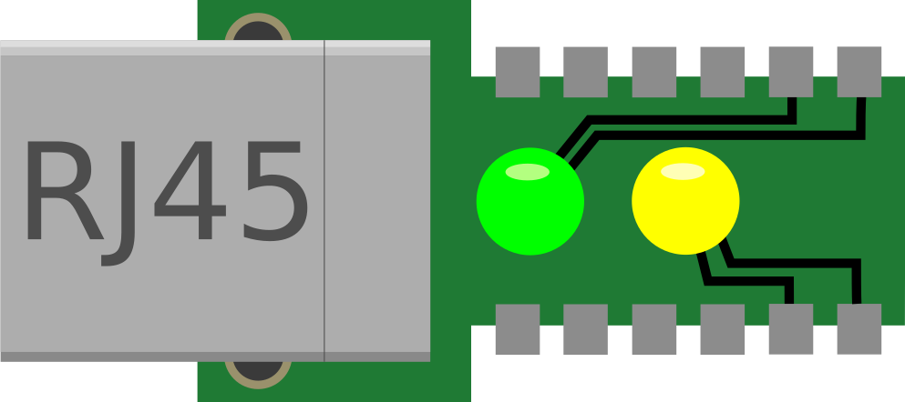
 Design with RJ45-TRXCOM in Cirkit Designer
Introduction
The RJ45-TRXCOM (Manufacturer Part ID: TRJ0011BANL) is a high-performance Ethernet connector designed for reliable data transmission in networking applications. Manufactured by TRXCOM, this component is widely used in local area networks (LANs) to connect devices via twisted pair cables. It features an 8-pin configuration, making it suitable for Ethernet standards such as 10BASE-T, 100BASE-TX, and 1000BASE-T (Gigabit Ethernet).
Explore Projects Built with RJ45-TRXCOM
 Open Project in Cirkit Designer
 Open Project in Cirkit Designer
 Open Project in Cirkit Designer
 Open Project in Cirkit Designer
Explore Projects Built with RJ45-TRXCOM
Open Project in Cirkit DesignerOpen Project in Cirkit DesignerOpen Project in Cirkit DesignerOpen Project in Cirkit DesignerCommon Applications and Use Cases
- Ethernet networking in home and office environments
- Routers, switches, and hubs
- Industrial Ethernet applications
- IoT devices requiring network connectivity
- Embedded systems with Ethernet interfaces
Technical Specifications
Key Technical Details
| Parameter | Value |
|---|---|
| Manufacturer | TRXCOM |
| Part ID | TRJ0011BANL |
| Connector Type | RJ45 |
| Number of Pins | 8 |
| Ethernet Standards | 10BASE-T, 100BASE-TX, 1000BASE-T |
| Mounting Type | Through-hole |
| Shielding | Yes |
| Operating Temperature | -40°C to +85°C |
| Contact Resistance | ≤ 20 mΩ |
| Insulation Resistance | ≥ 500 MΩ |
| Voltage Rating | 125V AC |
| Current Rating | 1.5A |
Pin Configuration and Descriptions
The RJ45-TRXCOM connector features eight pins, each corresponding to a specific signal in Ethernet communication. The pinout is as follows:
| Pin Number | Signal Name | Description |
|---|---|---|
| 1 | TX+ | Transmit Data Positive |
| 2 | TX- | Transmit Data Negative |
| 3 | RX+ | Receive Data Positive |
| 4 | BI_D3+ | Bidirectional Data Pair 3 Positive |
| 5 | BI_D3- | Bidirectional Data Pair 3 Negative |
| 6 | RX- | Receive Data Negative |
| 7 | BI_D4+ | Bidirectional Data Pair 4 Positive |
| 8 | BI_D4- | Bidirectional Data Pair 4 Negative |
Usage Instructions
How to Use the Component in a Circuit
- Mounting the Connector: The RJ45-TRXCOM is a through-hole component. Ensure the PCB has appropriately sized holes for the connector pins. Solder the pins securely to the PCB.
- Connecting Ethernet Cables: Insert a standard Ethernet cable (e.g., Cat5e or Cat6) into the RJ45 connector until it clicks into place.
- Signal Traces: Route the PCB traces for the TX, RX, and bidirectional data pairs according to the Ethernet standard being used. Maintain proper impedance matching for high-speed signals.
- Shielding: Connect the shielding pin of the RJ45 connector to the ground plane of the PCB to reduce electromagnetic interference (EMI).
Important Considerations and Best Practices
- Signal Integrity: Use differential pairs for TX and RX signals to minimize noise and crosstalk.
- PCB Layout: Keep the traces for Ethernet signals as short and direct as possible. Avoid sharp bends and ensure proper spacing between differential pairs.
- Power Supply: If using Power over Ethernet (PoE), ensure the PCB design complies with the PoE standard and that the RJ45 connector can handle the required current.
- Environmental Conditions: Verify that the operating temperature and humidity of the environment are within the specified range for the RJ45-TRXCOM.
Example: Connecting to an Arduino UNO
The RJ45-TRXCOM can be used with an Ethernet shield to connect an Arduino UNO to a network. Below is an example Arduino sketch for basic Ethernet communication:
#include <SPI.h>
#include <Ethernet.h>

// MAC address for the Ethernet shield
byte mac[] = { 0xDE, 0xAD, 0xBE, 0xEF, 0xFE, 0xED };

// IP address for the Arduino
IPAddress ip(192, 168, 1, 177);

// Initialize the Ethernet server on port 80
EthernetServer server(80);

void setup() {
  // Start the Ethernet connection
  Ethernet.begin(mac, ip);

  // Start the server
  server.begin();

  // Print the IP address to the serial monitor
  Serial.begin(9600);
  Serial.print("Server is at ");
  Serial.println(Ethernet.localIP());
}

void loop() {
  // Listen for incoming clients
  EthernetClient client = server.available();
  if (client) {
    Serial.println("New client connected");
    while (client.connected()) {
      if (client.available()) {
        char c = client.read();
        Serial.write(c); // Echo the received data to the serial monitor
        // Respond to the client
        client.println("Hello from Arduino!");
      }
    }
    client.stop();
    Serial.println("Client disconnected");
  }
}
Troubleshooting and FAQs
Common Issues Users Might Face
No Ethernet Connection:
- Cause: Improper soldering or loose cable connection.
- Solution: Check the solder joints and ensure the Ethernet cable is securely connected.
High Signal Noise or Crosstalk:
- Cause: Poor PCB layout or improper shielding.
- Solution: Re-route the signal traces to maintain proper spacing and connect the shielding pin to the ground plane.
Overheating:
- Cause: Exceeding the current or voltage rating.
- Solution: Ensure the component operates within its specified ratings.
Intermittent Connectivity:
- Cause: Faulty Ethernet cable or damaged connector pins.
- Solution: Replace the cable and inspect the connector for physical damage.
Solutions and Tips for Troubleshooting
- Use a multimeter to check continuity between the pins and the PCB traces.
- Verify the Ethernet cable's integrity using a cable tester.
- Ensure the RJ45-TRXCOM is compatible with the Ethernet standard being used.
- For PoE applications, confirm that the power supply and PCB design meet the required specifications.
By following this documentation, users can effectively integrate the RJ45-TRXCOM into their networking projects and troubleshoot common issues with ease.