How to Use 4 channel USB buck convertor: Examples, Pinouts, and Specs
Introduction
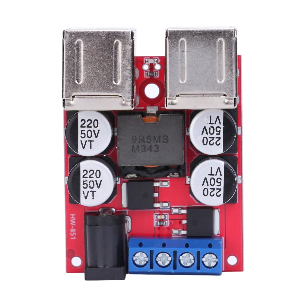
A 4 channel USB buck converter is a versatile power management device designed to step down voltage from a higher input level to a lower, regulated output level. It features four independent channels, each capable of providing power to USB-powered devices. This component is widely used in applications requiring efficient power distribution, such as charging multiple devices, powering microcontrollers, or supplying power to sensors and peripherals.
Explore Projects Built with 4 channel USB buck convertor


Explore Projects Built with 4 channel USB buck convertor
Common Applications and Use Cases
- Charging multiple USB devices simultaneously
- Powering microcontrollers, such as Arduino or Raspberry Pi
- Supplying power to sensors, actuators, and other peripherals
- Use in DIY electronics projects and prototyping
- Power management in automotive or industrial systems
Technical Specifications
Below are the key technical details for the 4 channel USB buck converter:
| Parameter | Value |
|---|---|
| Input Voltage Range | 6V to 24V |
| Output Voltage (per USB) | 5V (regulated) |
| Maximum Output Current | 2A per channel |
| Number of Channels | 4 |
| Efficiency | Up to 95% (depending on load conditions) |
| USB Port Type | USB Type-A |
| Protection Features | Overcurrent, overvoltage, and short-circuit |
Pin Configuration and Descriptions
The 4 channel USB buck converter typically has the following input and output connections:
| Pin/Port | Description |
|---|---|
| VIN+ | Positive input voltage terminal (6V to 24V) |
| VIN- | Negative input voltage terminal (ground) |
| USB1 | 5V output for Channel 1 |
| USB2 | 5V output for Channel 2 |
| USB3 | 5V output for Channel 3 |
| USB4 | 5V output for Channel 4 |
Usage Instructions
How to Use the Component in a Circuit
Connect the Input Voltage:
- Attach the positive terminal of your power source (6V to 24V) to the
VIN+pin. - Connect the negative terminal of your power source to the
VIN-pin.
- Attach the positive terminal of your power source (6V to 24V) to the
Connect USB Devices:
- Plug your USB-powered devices into the USB ports (USB1, USB2, USB3, USB4).
- Ensure that the total current draw does not exceed the maximum rating of 2A per channel.
Power On:
- Turn on the power source. The buck converter will regulate the input voltage to provide a stable 5V output to each USB port.
Important Considerations and Best Practices
- Input Voltage Range: Ensure the input voltage is within the specified range (6V to 24V). Exceeding this range may damage the converter.
- Current Limitations: Do not exceed 2A per channel. Overloading a channel may trigger the overcurrent protection or damage the device.
- Heat Dissipation: If the converter is used at high currents for extended periods, ensure proper ventilation or add a heatsink to prevent overheating.
- Polarity: Double-check the polarity of the input voltage to avoid damage to the converter.
Example: Using with an Arduino UNO
The 4 channel USB buck converter can be used to power an Arduino UNO. Below is an example of how to connect and use it:
- Connect the
VIN+andVIN-pins of the buck converter to a 12V DC power supply. - Plug the Arduino UNO into one of the USB ports (e.g., USB1).
- The buck converter will provide a stable 5V output to power the Arduino.
Here is a simple Arduino sketch to blink an LED, assuming the Arduino is powered via the buck converter:
// Simple LED Blink Example
// This code blinks an LED connected to pin 13 of the Arduino UNO.
// Ensure the Arduino is powered via the 4 channel USB buck converter.

void setup() {
  pinMode(13, OUTPUT); // Set pin 13 as an output
}

void loop() {
  digitalWrite(13, HIGH); // Turn the LED on
  delay(1000);            // Wait for 1 second
  digitalWrite(13, LOW);  // Turn the LED off
  delay(1000);            // Wait for 1 second
}
Troubleshooting and FAQs
Common Issues and Solutions
No Output Voltage:
- Cause: Input voltage is not connected or is outside the specified range.
- Solution: Verify the input voltage is between 6V and 24V and check the connections.
Overheating:
- Cause: Excessive current draw or poor ventilation.
- Solution: Reduce the load on the USB ports or improve ventilation around the converter.
Device Not Charging:
- Cause: USB device requires more than 2A or is incompatible.
- Solution: Ensure the device's current requirements are within the 2A limit.
Short Circuit Protection Triggered:
- Cause: A short circuit occurred on one of the USB ports.
- Solution: Disconnect all devices, check for shorts, and reconnect after resolving the issue.
FAQs
Q: Can I use this converter to power a Raspberry Pi?
A: Yes, the 4 channel USB buck converter can power a Raspberry Pi, as it provides a stable 5V output. Ensure the current draw does not exceed 2A.
Q: Can I connect all four USB ports simultaneously?
A: Yes, you can use all four USB ports at the same time, provided the total current draw does not exceed the maximum rating of 2A per channel.
Q: Is the converter safe to use with sensitive electronics?
A: Yes, the converter includes protection features such as overcurrent, overvoltage, and short-circuit protection, making it safe for sensitive devices.
Q: Can I use this converter with a solar panel?
A: Yes, as long as the solar panel provides a stable voltage within the 6V to 24V range, the converter can step it down to 5V for USB devices.