How to Use ESP32 (30 pin, Sized correctly) back: Examples, Pinouts, and Specs
Introduction
The ESP32, manufactured by Espressif, is a powerful and versatile microcontroller that integrates both Wi-Fi and Bluetooth capabilities. With its 30-pin configuration, the ESP32 is designed to support a wide range of applications, from IoT (Internet of Things) devices to home automation, robotics, and wearable electronics. Its compact size and robust processing power make it a popular choice for developers and hobbyists alike.
Explore Projects Built with ESP32 (30 pin, Sized correctly) back

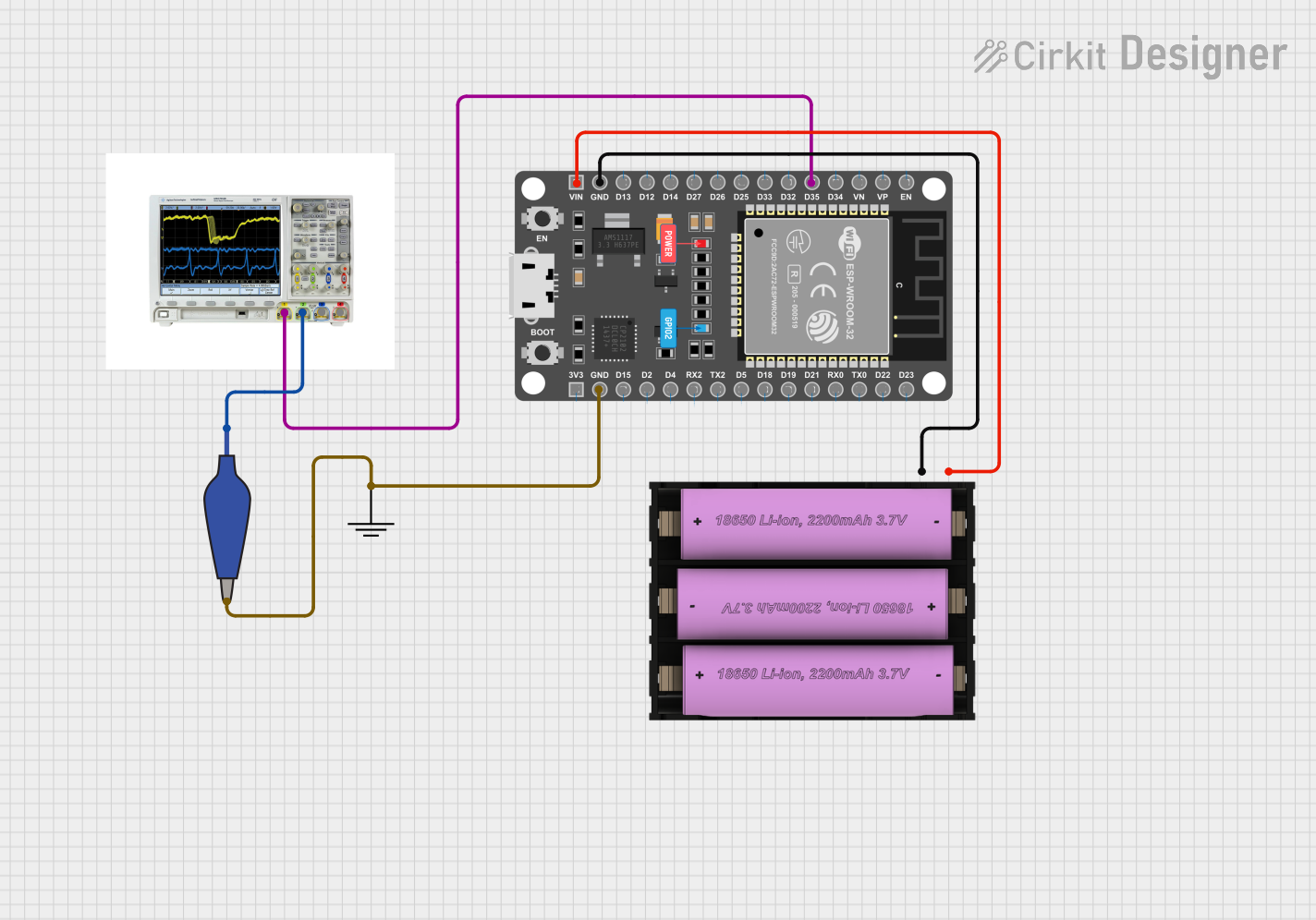


Explore Projects Built with ESP32 (30 pin, Sized correctly) back
Common Applications and Use Cases
- IoT devices and smart home systems
- Wireless sensor networks
- Robotics and automation
- Wearable technology
- Data logging and remote monitoring
- Prototyping and educational projects
Technical Specifications
The ESP32 (30-pin variant) offers a rich set of features and specifications that make it suitable for a variety of applications. Below are the key technical details:
General Specifications
- Microcontroller: Dual-core Xtensa® 32-bit LX6
- Clock Speed: Up to 240 MHz
- Flash Memory: 4 MB (external)
- SRAM: 520 KB
- Wi-Fi: 802.11 b/g/n
- Bluetooth: v4.2 BR/EDR and BLE
- Operating Voltage: 3.3V
- Input Voltage Range: 5V (via USB) or 7-12V (via VIN pin)
- GPIO Pins: 30 pins (including ADC, DAC, PWM, I2C, SPI, UART)
- Power Consumption: Ultra-low power consumption in deep sleep mode (~10 µA)
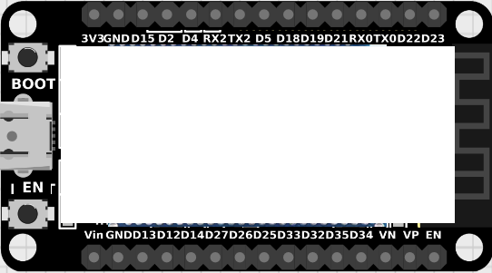
Pin Configuration and Descriptions
The ESP32 (30-pin variant) has a well-organized pinout. Below is a table describing the key pins:
| Pin Name | Type | Description |
|---|---|---|
| VIN | Power Input | Input voltage (7-12V) for powering the ESP32. |
| 3V3 | Power Output | Regulated 3.3V output from the onboard voltage regulator. |
| GND | Ground | Ground connection. |
| EN | Enable | Enables the chip when pulled high. |
| GPIO0 | GPIO | General-purpose I/O pin; also used for boot mode selection. |
| GPIO2 | GPIO | General-purpose I/O pin. |
| GPIO4 | GPIO | General-purpose I/O pin. |
| GPIO5 | GPIO | General-purpose I/O pin. |
| GPIO12 | GPIO | General-purpose I/O pin; also used for bootstrapping. |
| GPIO13 | GPIO | General-purpose I/O pin. |
| GPIO14 | GPIO | General-purpose I/O pin. |
| GPIO15 | GPIO | General-purpose I/O pin. |
| GPIO16 | GPIO | General-purpose I/O pin. |
| GPIO17 | GPIO | General-purpose I/O pin. |
| GPIO18 | GPIO | General-purpose I/O pin; supports SPI clock (SCK). |
| GPIO19 | GPIO | General-purpose I/O pin; supports SPI MISO. |
| GPIO21 | GPIO | General-purpose I/O pin; supports I2C SDA. |
| GPIO22 | GPIO | General-purpose I/O pin; supports I2C SCL. |
| GPIO23 | GPIO | General-purpose I/O pin; supports SPI MOSI. |
| GPIO25 | GPIO | General-purpose I/O pin; supports DAC output. |
| GPIO26 | GPIO | General-purpose I/O pin; supports DAC output. |
| GPIO27 | GPIO | General-purpose I/O pin. |
| GPIO32 | GPIO | General-purpose I/O pin; supports ADC input. |
| GPIO33 | GPIO | General-purpose I/O pin; supports ADC input. |
| GPIO34 | GPIO (Input) | General-purpose input pin; supports ADC input. |
| GPIO35 | GPIO (Input) | General-purpose input pin; supports ADC input. |
| GPIO36 | GPIO (Input) | General-purpose input pin; supports ADC input. |
| GPIO39 | GPIO (Input) | General-purpose input pin; supports ADC input. |
| TX0 | UART TX | UART0 transmit pin. |
| RX0 | UART RX | UART0 receive pin. |
Usage Instructions
The ESP32 is easy to integrate into a variety of projects. Below are the steps and best practices for using the ESP32 in a circuit.
Basic Setup
Powering the ESP32:
- Use the VIN pin to supply 7-12V, or connect a USB cable to the micro-USB port for 5V input.
- Ensure the 3V3 pin is used only for low-power peripherals, as it provides regulated 3.3V output.
Connecting to a Computer:
- Install the necessary USB-to-serial drivers (e.g., CP2102 or CH340, depending on your ESP32 board).
- Use the Arduino IDE or Espressif's ESP-IDF for programming.
Programming the ESP32:
- Select the correct board in the Arduino IDE (
Tools > Board > ESP32 Dev Module). - Connect the ESP32 to your computer via USB and select the appropriate COM port.
- Select the correct board in the Arduino IDE (
Example: Blinking an LED
The following example demonstrates how to blink an LED connected to GPIO2 using the Arduino IDE:
// Define the GPIO pin where the LED is connected
#define LED_PIN 2

void setup() {
  // Set the LED pin as an output
  pinMode(LED_PIN, OUTPUT);
}

void loop() {
  // Turn the LED on
  digitalWrite(LED_PIN, HIGH);
  delay(1000); // Wait for 1 second

  // Turn the LED off
  digitalWrite(LED_PIN, LOW);
  delay(1000); // Wait for 1 second
}
Important Considerations
- Voltage Levels: The ESP32 operates at 3.3V logic levels. Avoid connecting 5V signals directly to its GPIO pins.
- Boot Mode: Ensure GPIO0 is pulled low during boot to enter programming mode.
- Power Supply: Use a stable power source to avoid unexpected resets or malfunctions.
Troubleshooting and FAQs
Common Issues
ESP32 Not Detected by Computer:
- Ensure the correct USB-to-serial driver is installed.
- Check the USB cable for data transfer capability (some cables are power-only).
Program Upload Fails:
- Verify that GPIO0 is pulled low during programming.
- Check the selected COM port and board type in the Arduino IDE.
Wi-Fi Connection Issues:
- Ensure the correct SSID and password are used in your code.
- Check for interference or weak signal strength.
Random Resets:
- Verify that the power supply is stable and capable of providing sufficient current (at least 500 mA).
Tips for Troubleshooting
- Use the serial monitor in the Arduino IDE to debug and view error messages.
- Test the ESP32 with a simple program (e.g., blinking an LED) to verify basic functionality.
- Double-check all connections and ensure no pins are shorted.
By following this documentation, you can effectively utilize the ESP32 (30-pin variant) in your projects and troubleshoot common issues with ease.