
How to Use ardino uno r3: Examples, Pinouts, and Specs
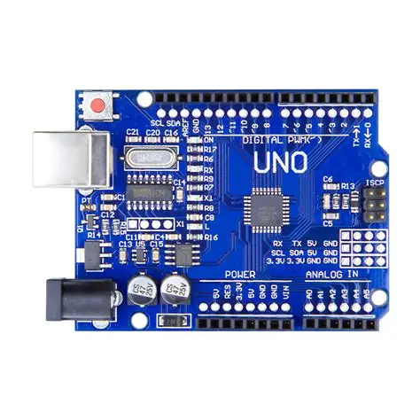
 Design with ardino uno r3 in Cirkit Designer
Introduction
The Arduino Uno R3 is a microcontroller board based on the ATmega328P. It features 14 digital input/output pins (6 of which can be used as PWM outputs), 6 analog inputs, a USB connection for programming, a power jack, an ICSP header, and a reset button. This board is widely used for prototyping and embedded projects due to its simplicity, versatility, and extensive community support.
Explore Projects Built with ardino uno r3
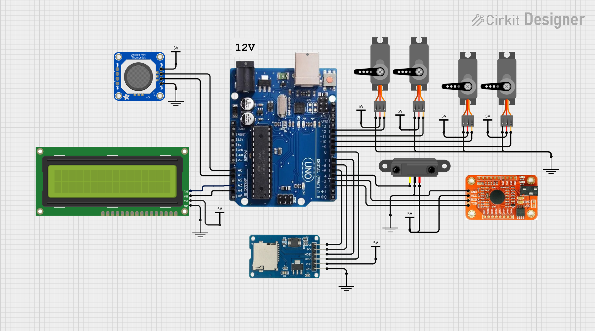 Open Project in Cirkit Designer
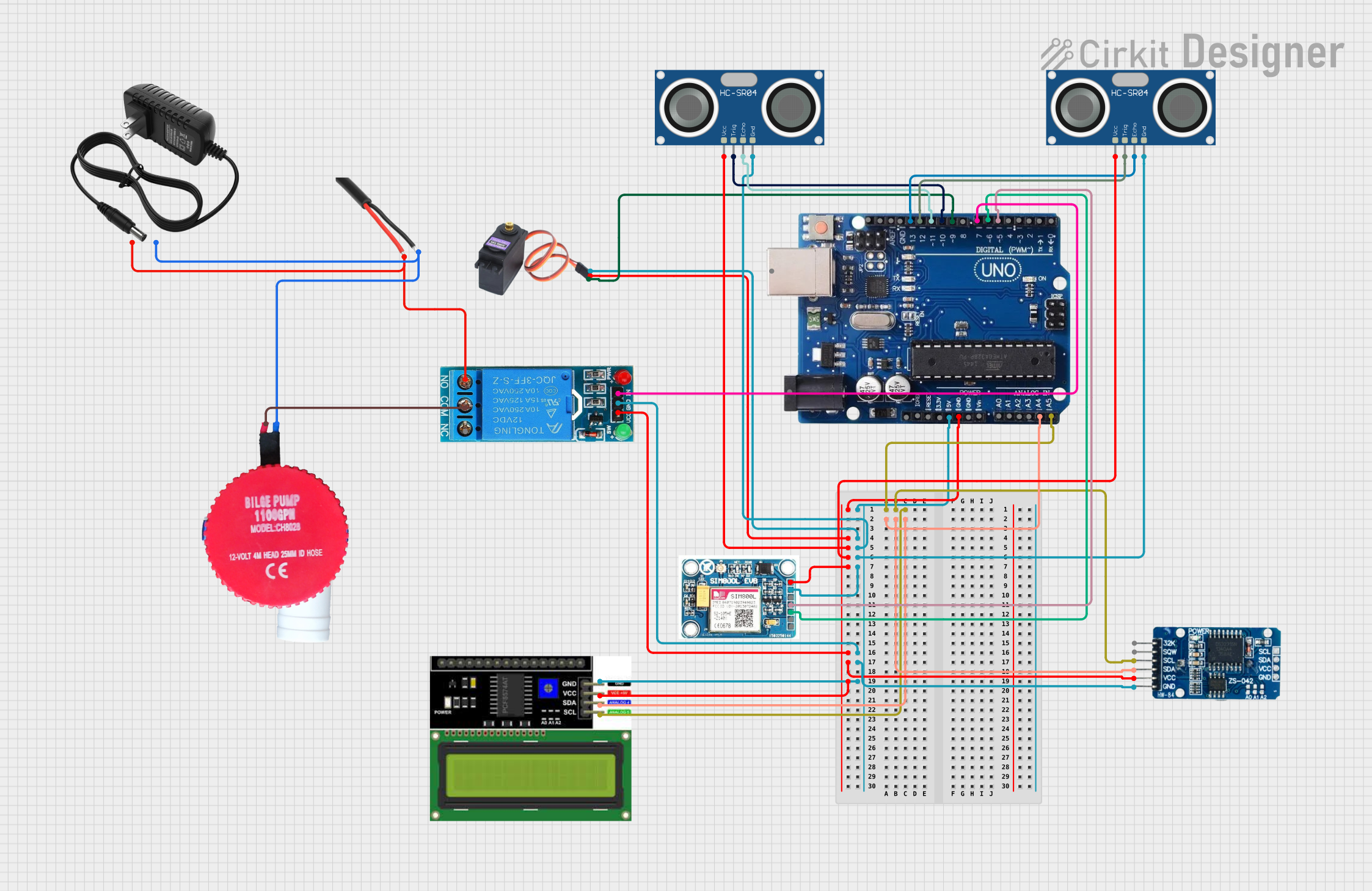 Open Project in Cirkit Designer
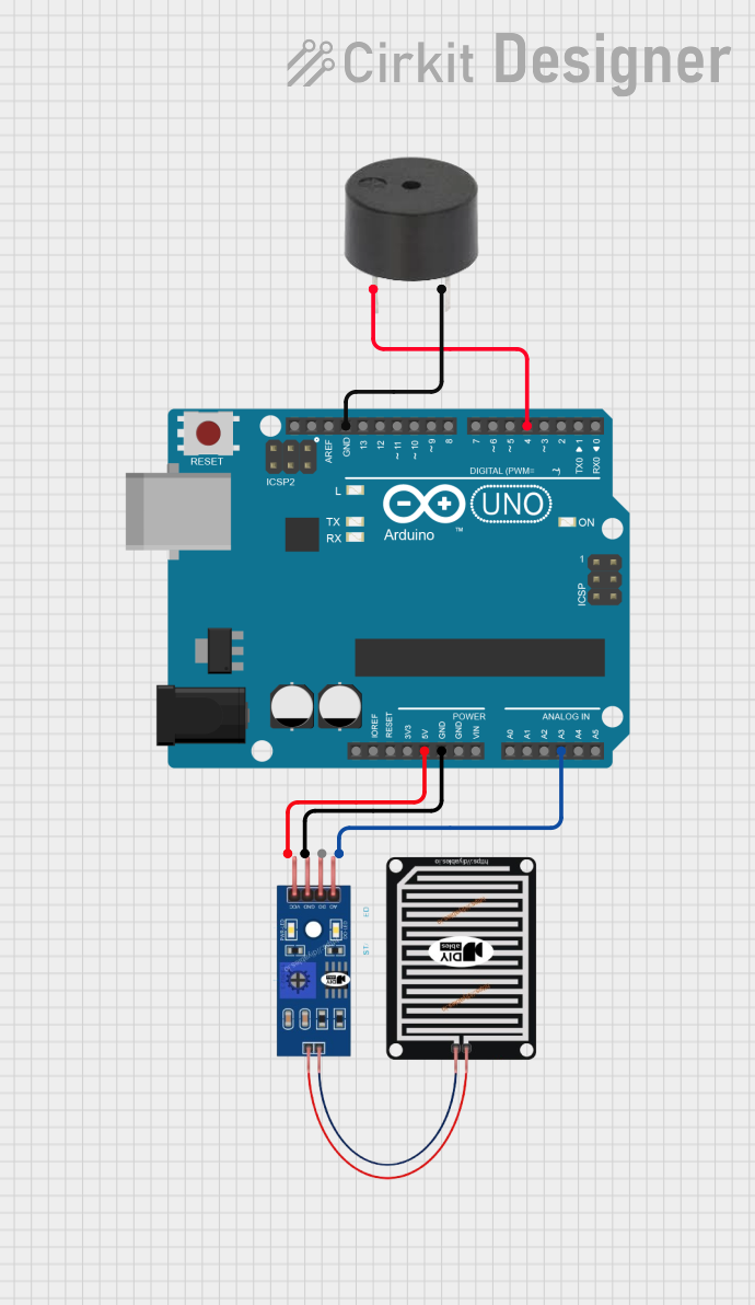 Open Project in Cirkit Designer
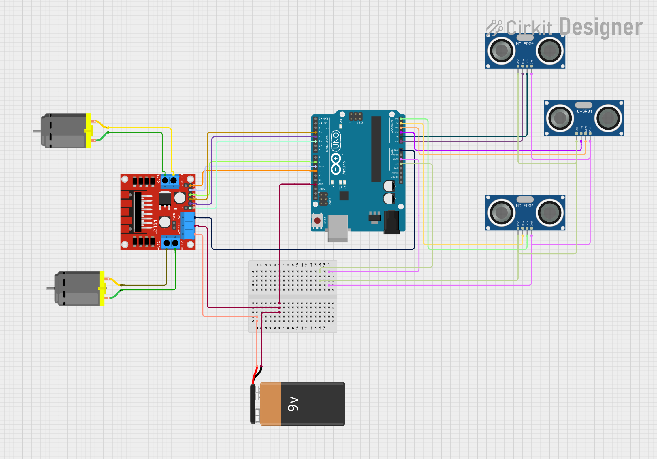 Open Project in Cirkit Designer
Explore Projects Built with ardino uno r3
Open Project in Cirkit DesignerOpen Project in Cirkit DesignerOpen Project in Cirkit DesignerOpen Project in Cirkit DesignerCommon Applications and Use Cases
- Prototyping electronic circuits
- Building IoT (Internet of Things) devices
- Robotics and automation projects
- Sensor data acquisition and processing
- Educational purposes for learning programming and electronics
Technical Specifications
Key Technical Details
| Specification | Value |
|---|---|
| Microcontroller | ATmega328P |
| Operating Voltage | 5V |
| Input Voltage (recommended) | 7-12V |
| Input Voltage (limit) | 6-20V |
| Digital I/O Pins | 14 (6 PWM outputs) |
| Analog Input Pins | 6 |
| DC Current per I/O Pin | 20 mA |
| Flash Memory | 32 KB (0.5 KB used by bootloader) |
| SRAM | 2 KB |
| EEPROM | 1 KB |
| Clock Speed | 16 MHz |
| USB Connector | Type-B |
| Dimensions | 68.6 mm x 53.4 mm |
| Weight | 25 g |
Pin Configuration and Descriptions
| Pin Number | Pin Name | Description |
|---|---|---|
| 1-14 | Digital Pins | General-purpose digital I/O pins. Pins 3, 5, 6, 9, 10, and 11 support PWM. |
| A0-A5 | Analog Pins | Analog input pins for reading sensor data (10-bit resolution). |
| GND | Ground | Ground connection for the circuit. |
| 5V | 5V Power | Provides regulated 5V output. |
| 3.3V | 3.3V Power | Provides regulated 3.3V output. |
| VIN | Voltage Input | Input voltage to the board when using an external power source. |
| RESET | Reset | Resets the microcontroller. |
| ICSP | ICSP Header | Used for in-circuit serial programming of the microcontroller. |
| TX/RX | Serial Pins | TX (pin 1) and RX (pin 0) for serial communication. |
Usage Instructions
How to Use the Arduino Uno R3 in a Circuit
Powering the Board:
- Connect the board to your computer using a USB Type-B cable for programming and power.
- Alternatively, use an external power source (7-12V) via the power jack or VIN pin.
Programming the Board:
- Install the Arduino IDE from the official Arduino website.
- Connect the board to your computer via USB.
- Select "Arduino Uno" as the board type in the Arduino IDE.
- Write your code in the IDE and upload it to the board.
Connecting Components:
- Use the digital pins for controlling LEDs, relays, or other digital devices.
- Use the analog pins to read sensor data (e.g., temperature, light intensity).
- Ensure proper grounding and voltage levels to avoid damaging the board.
Important Considerations and Best Practices
- Avoid exceeding the maximum current rating (20 mA) for each I/O pin.
- Use resistors with LEDs to limit current and prevent damage.
- When using motors or high-power devices, use external power supplies and transistors or relays.
- Always double-check connections to avoid short circuits.
Example Code for Blinking an LED
// This example code blinks an LED connected to digital pin 13.
// The LED will turn on for 1 second and off for 1 second repeatedly.

void setup() {
  pinMode(13, OUTPUT); // Set digital pin 13 as an output pin
}

void loop() {
  digitalWrite(13, HIGH); // Turn the LED on
  delay(1000);            // Wait for 1 second
  digitalWrite(13, LOW);  // Turn the LED off
  delay(1000);            // Wait for 1 second
}
Troubleshooting and FAQs
Common Issues and Solutions
The board is not detected by the computer:
- Ensure the USB cable is properly connected and functional.
- Check if the correct COM port is selected in the Arduino IDE.
- Install or update the USB drivers for the Arduino Uno.
Code does not upload to the board:
- Verify that "Arduino Uno" is selected as the board type in the IDE.
- Ensure no other program is using the COM port.
- Press the reset button on the board before uploading.
The board is not powering on:
- Check the power source and connections.
- Ensure the input voltage is within the recommended range (7-12V).
Components connected to the board are not working:
- Verify the wiring and connections.
- Check if the components are functional and compatible with the Arduino Uno.
- Ensure the code logic is correct and matches the circuit design.
FAQs
Q: Can I power the Arduino Uno R3 with a battery?
A: Yes, you can use a 9V battery connected to the power jack or VIN pin. Ensure the voltage is within the 7-12V range.
Q: What is the maximum current the board can supply?
A: The 5V and 3.3V pins can supply a maximum of 500 mA and 50 mA, respectively, when powered via USB.
Q: Can I use the Arduino Uno R3 for wireless communication?
A: Yes, you can use external modules like Bluetooth (HC-05/HC-06) or Wi-Fi (ESP8266) for wireless communication.
Q: Is the Arduino Uno R3 compatible with shields?
A: Yes, the Arduino Uno R3 is compatible with a wide range of shields designed for the Uno form factor.