Cirkit Designer Logo
Cirkit Designer
Your all-in-one circuit design IDE
Home / 
Component Documentation

How to Use SIK Telemetry Radio: Examples, Pinouts, and Specs

Image of SIK Telemetry Radio
Cirkit Designer LogoDesign with SIK Telemetry Radio in Cirkit Designer

Introduction

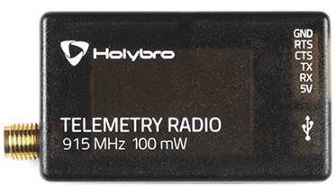
The SIK Telemetry Radio is a compact and reliable radio module designed for long-range telemetry communication. Manufactured by SIK, this module is widely used in applications requiring real-time data transmission, such as drones, robotics, and remote monitoring systems. It enables seamless communication between a ground control station and a remote device, transmitting data like GPS coordinates, sensor readings, and system diagnostics.

With its robust design and ease of integration, the SIK Telemetry Radio is a popular choice for hobbyists and professionals alike. It supports bidirectional communication, making it ideal for applications where both control commands and telemetry data need to be exchanged.

Explore Projects Built with SIK Telemetry Radio

Use Cirkit Designer to design, explore, and prototype these projects online. Some projects support real-time simulation. Click "Open Project" to start designing instantly!
Satellite-Based Timing and Navigation System with SDR and Atomic Clock Synchronization
Image of GPS 시스템 측정 구성도_Confirm: A project utilizing SIK Telemetry Radio in a practical application
This circuit appears to be a complex system involving power supply management, GPS and timing synchronization, and data communication. It includes a SI-TEX G1 Satellite Compass for GPS data, an XHTF1021 Atomic Rubidium Clock for precise timing, and Ettus USRP B200 units for software-defined radio communication. Power is supplied through various SMPS units and distributed via terminal blocks and DC jacks. Data communication is facilitated by Beelink MINI S12 N95 computers, RS232 splitters, and a 1000BASE-T Media Converter for network connectivity. RF Directional Couplers are used to interface antennas with the USRP units, and the entire system is likely contained within cases for protection and organization.
Cirkit Designer LogoOpen Project in Cirkit Designer
ESP32 and TEA5767 FM Radio with ILI9341 Display and Potentiometer Tuning
Image of v1: A project utilizing SIK Telemetry Radio in a practical application
This circuit is an FM radio receiver with a TEA5767 tuner module controlled by an ESP32 microcontroller. The ESP32 reads the frequency input from a rotary potentiometer and displays the current frequency on an ILI9341 TFT display. The microcontroller adjusts the tuner frequency via I2C communication based on the potentiometer's position.
Cirkit Designer LogoOpen Project in Cirkit Designer
Raspberry Pi and H743-SLIM V3 Controlled Servo System with GPS and Telemetry
Image of Avionics Wiring Diagram: A project utilizing SIK Telemetry Radio in a practical application
This circuit is designed for a UAV control system, featuring an H743-SLIM V3 flight controller connected to multiple servos for control surfaces, a GPS module for navigation, a telemetry radio for communication, and a digital airspeed sensor for flight data. The system is powered by a LiPo battery and includes a Raspberry Pi for additional processing and control tasks.
Cirkit Designer LogoOpen Project in Cirkit Designer
Dual-Mode LoRa and GSM Communication Device with ESP32
Image of modul gateway: A project utilizing SIK Telemetry Radio in a practical application
This circuit features an ESP32 Devkit V1 microcontroller interfaced with an RFM95 LoRa transceiver module for long-range communication and a SIM800L GSM module for cellular connectivity. Two LM2596 step-down modules are used to regulate the 12V battery voltage down to 3.3V required by the ESP32, RFM95, and SIM800L. The ESP32 facilitates data exchange between the RFM95 and SIM800L, enabling the system to send/receive data over both LoRa and GSM networks.
Cirkit Designer LogoOpen Project in Cirkit Designer

Explore Projects Built with SIK Telemetry Radio

Use Cirkit Designer to design, explore, and prototype these projects online. Some projects support real-time simulation. Click "Open Project" to start designing instantly!
Image of GPS 시스템 측정 구성도_Confirm: A project utilizing SIK Telemetry Radio in a practical application
Satellite-Based Timing and Navigation System with SDR and Atomic Clock Synchronization
This circuit appears to be a complex system involving power supply management, GPS and timing synchronization, and data communication. It includes a SI-TEX G1 Satellite Compass for GPS data, an XHTF1021 Atomic Rubidium Clock for precise timing, and Ettus USRP B200 units for software-defined radio communication. Power is supplied through various SMPS units and distributed via terminal blocks and DC jacks. Data communication is facilitated by Beelink MINI S12 N95 computers, RS232 splitters, and a 1000BASE-T Media Converter for network connectivity. RF Directional Couplers are used to interface antennas with the USRP units, and the entire system is likely contained within cases for protection and organization.
Cirkit Designer LogoOpen Project in Cirkit Designer
Image of v1: A project utilizing SIK Telemetry Radio in a practical application
ESP32 and TEA5767 FM Radio with ILI9341 Display and Potentiometer Tuning
This circuit is an FM radio receiver with a TEA5767 tuner module controlled by an ESP32 microcontroller. The ESP32 reads the frequency input from a rotary potentiometer and displays the current frequency on an ILI9341 TFT display. The microcontroller adjusts the tuner frequency via I2C communication based on the potentiometer's position.
Cirkit Designer LogoOpen Project in Cirkit Designer
Image of Avionics Wiring Diagram: A project utilizing SIK Telemetry Radio in a practical application
Raspberry Pi and H743-SLIM V3 Controlled Servo System with GPS and Telemetry
This circuit is designed for a UAV control system, featuring an H743-SLIM V3 flight controller connected to multiple servos for control surfaces, a GPS module for navigation, a telemetry radio for communication, and a digital airspeed sensor for flight data. The system is powered by a LiPo battery and includes a Raspberry Pi for additional processing and control tasks.
Cirkit Designer LogoOpen Project in Cirkit Designer
Image of modul gateway: A project utilizing SIK Telemetry Radio in a practical application
Dual-Mode LoRa and GSM Communication Device with ESP32
This circuit features an ESP32 Devkit V1 microcontroller interfaced with an RFM95 LoRa transceiver module for long-range communication and a SIM800L GSM module for cellular connectivity. Two LM2596 step-down modules are used to regulate the 12V battery voltage down to 3.3V required by the ESP32, RFM95, and SIM800L. The ESP32 facilitates data exchange between the RFM95 and SIM800L, enabling the system to send/receive data over both LoRa and GSM networks.
Cirkit Designer LogoOpen Project in Cirkit Designer

Common Applications

  • Drones and UAVs for transmitting flight data and receiving control commands.
  • Robotics for real-time sensor data communication.
  • Remote monitoring systems for environmental or industrial data collection.
  • Ground control stations for telemetry and diagnostics.

Technical Specifications

Key Technical Details

  • Frequency Range: 433 MHz or 915 MHz (region-specific)
  • Communication Protocol: Transparent serial link
  • Data Rate: Up to 250 kbps
  • Range: Up to 1.5 km (line of sight, depending on antenna and environment)
  • Power Supply Voltage: 3.3V to 5V
  • Transmit Power: 100 mW (20 dBm)
  • Interface: UART (TTL level)
  • Antenna Connector: RP-SMA
  • Dimensions: 25 mm x 55 mm x 12 mm (excluding antenna)
  • Operating Temperature: -40°C to 85°C

Pin Configuration and Descriptions

The SIK Telemetry Radio module typically has a 6-pin header for interfacing. Below is the pinout:

Pin Name Description
1 GND Ground connection. Connect to the ground of the power supply or circuit.
2 VCC Power supply input (3.3V to 5V).
3 TX Transmit data (UART output). Connect to the RX pin of the microcontroller.
4 RX Receive data (UART input). Connect to the TX pin of the microcontroller.
5 CTS Clear to Send (optional, for hardware flow control).
6 RTS Request to Send (optional, for hardware flow control).

Usage Instructions

How to Use the SIK Telemetry Radio in a Circuit

  1. Power the Module: Connect the VCC pin to a 3.3V or 5V power source and the GND pin to the ground.
  2. Connect UART Pins:
    • Connect the TX pin of the SIK Telemetry Radio to the RX pin of your microcontroller or computer.
    • Connect the RX pin of the SIK Telemetry Radio to the TX pin of your microcontroller or computer.
  3. Antenna Setup: Attach the provided RP-SMA antenna to the module for optimal signal strength.
  4. Configure the Module: Use a configuration tool (e.g., Mission Planner or a terminal program) to set the frequency, baud rate, and other parameters. Ensure both the ground and air modules are configured identically.
  5. Test Communication: Verify the connection by sending and receiving data between the ground station and the remote device.

Important Considerations and Best Practices

  • Antenna Placement: Ensure the antenna is mounted vertically and away from obstructions for maximum range.
  • Power Supply: Use a stable power source to avoid communication interruptions.
  • Baud Rate Matching: Ensure the baud rate of the SIK Telemetry Radio matches the baud rate of the connected device.
  • Line of Sight: For maximum range, maintain a clear line of sight between the ground and air modules.
  • Firmware Updates: Periodically check for firmware updates to ensure optimal performance and compatibility.

Example: Connecting to an Arduino UNO

Below is an example of how to connect the SIK Telemetry Radio to an Arduino UNO and send data:

Wiring

  • SIK TXArduino RX (Pin 0)
  • SIK RXArduino TX (Pin 1)
  • SIK VCCArduino 5V
  • SIK GNDArduino GND

Code

// Example code to send data from Arduino to SIK Telemetry Radio
void setup() {
  Serial.begin(57600); // Initialize UART communication at 57600 baud
  delay(1000);         // Wait for the module to initialize
}

void loop() {
  Serial.println("Hello from Arduino!"); // Send a test message
  delay(1000);                           // Wait 1 second before sending again
}

Troubleshooting and FAQs

Common Issues and Solutions

  1. No Communication Between Modules

    • Cause: Mismatched baud rates or incorrect wiring.
    • Solution: Verify that both modules are configured with the same baud rate and check the TX/RX connections.
  2. Short Range or Signal Loss

    • Cause: Poor antenna placement or interference.
    • Solution: Ensure the antenna is mounted vertically and away from metal objects or other RF sources.
  3. Module Overheating

    • Cause: Prolonged high-power transmission.
    • Solution: Ensure adequate ventilation and avoid continuous high-power operation.
  4. Data Corruption

    • Cause: Noise or mismatched settings.
    • Solution: Use hardware flow control (CTS/RTS) if supported, and ensure proper grounding.

FAQs

  • Q: Can I use the SIK Telemetry Radio with a Raspberry Pi?

    • A: Yes, connect the TX/RX pins to the Raspberry Pi's UART pins and configure the serial port.
  • Q: What is the maximum range of the SIK Telemetry Radio?

    • A: The range can reach up to 1.5 km in ideal conditions with a clear line of sight.
  • Q: How do I update the firmware?

    • A: Use a configuration tool like Mission Planner to upload the latest firmware to the module.
  • Q: Can I use multiple SIK Telemetry Radios in the same area?

    • A: Yes, but ensure each pair operates on a unique frequency to avoid interference.

This concludes the documentation for the SIK Telemetry Radio. For further assistance, refer to the manufacturer's user manual or support resources.