
How to Use 7 Lower Pin Header: Examples, Pinouts, and Specs

 Design with 7 Lower Pin Header in Cirkit Designer
Introduction
The 7 Lower Pin Header is a type of electrical connector featuring seven pins arranged in a single row. It is commonly used in electronic circuits to establish secure and reliable connections between wires, components, or modules. This component is widely utilized in prototyping, PCB designs, and interfacing with microcontrollers or other devices. Its compact design and ease of use make it a staple in electronics projects.
Explore Projects Built with 7 Lower Pin Header
 Open Project in Cirkit Designer
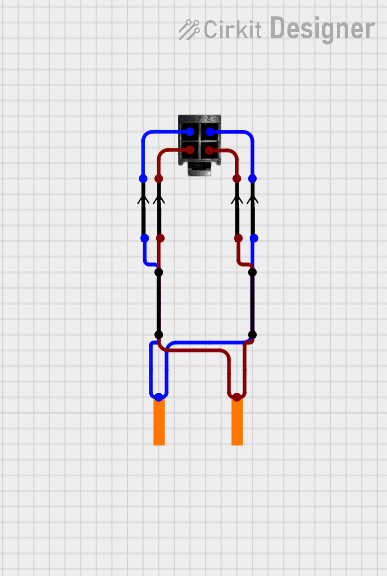 Open Project in Cirkit Designer
 Open Project in Cirkit Designer
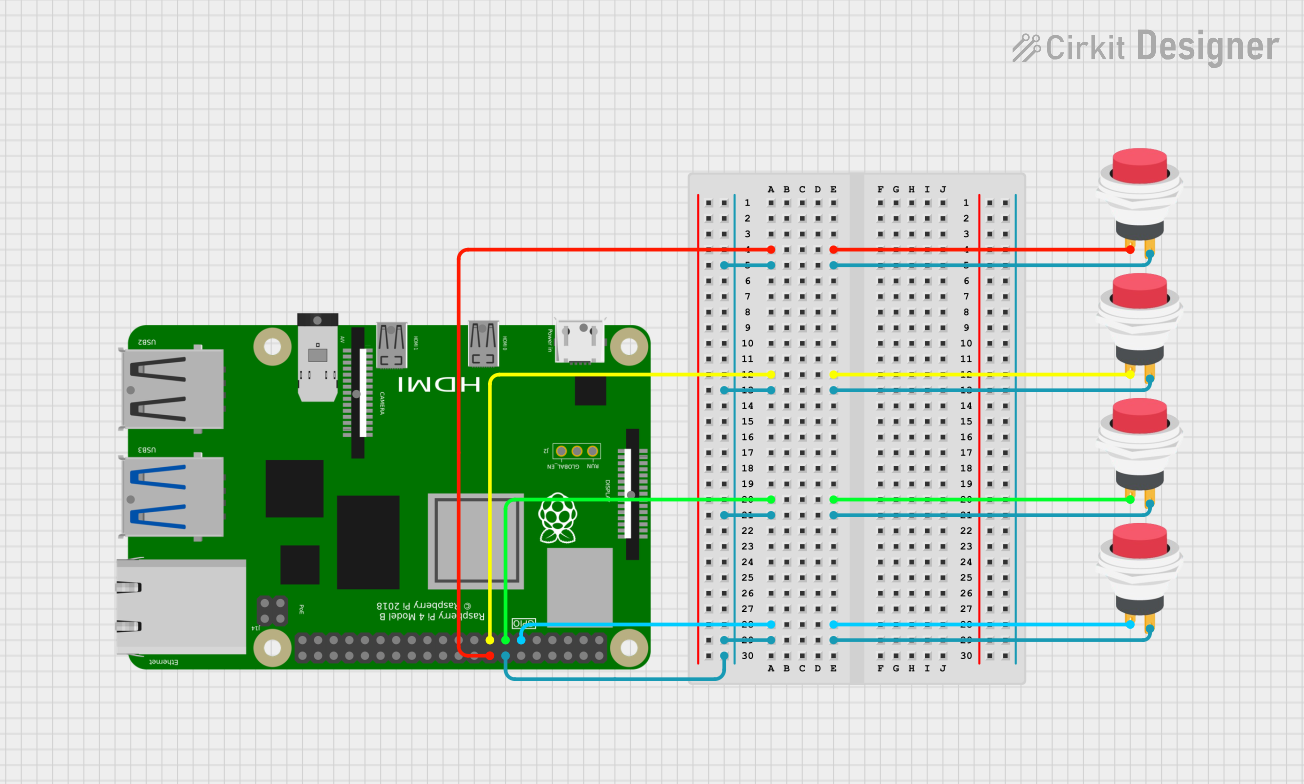 Open Project in Cirkit Designer
Explore Projects Built with 7 Lower Pin Header
Open Project in Cirkit DesignerOpen Project in Cirkit DesignerOpen Project in Cirkit DesignerOpen Project in Cirkit DesignerCommon Applications
- Connecting modules or sensors to microcontrollers (e.g., Arduino, Raspberry Pi)
- Prototyping and breadboard connections
- PCB-to-PCB or PCB-to-wire connections
- Interfacing with displays, motors, or other peripherals
Technical Specifications
Key Specifications
| Parameter | Value |
|---|---|
| Number of Pins | 7 |
| Pin Pitch | 2.54 mm (standard spacing) |
| Current Rating | Typically 3A per pin |
| Voltage Rating | Up to 250V |
| Material | Brass or copper (pins), plastic (housing) |
| Operating Temperature | -40°C to +105°C |
| Mounting Type | Through-hole or soldered |
Pin Configuration and Descriptions
The 7 Lower Pin Header does not have specific pin functions, as it is a general-purpose connector. However, the pins are typically numbered sequentially from 1 to 7 for identification purposes. Below is an example of how the pins might be labeled:
| Pin Number | Description |
|---|---|
| 1 | General-purpose connection |
| 2 | General-purpose connection |
| 3 | General-purpose connection |
| 4 | General-purpose connection |
| 5 | General-purpose connection |
| 6 | General-purpose connection |
| 7 | General-purpose connection |
Usage Instructions
How to Use the 7 Lower Pin Header in a Circuit
- Mounting the Header:
- If using a breadboard, insert the pins into the breadboard holes.
- For PCB applications, solder the pins into the designated through-hole pads.
- Connecting Wires or Components:
- Use jumper wires or female connectors to attach components or modules to the header.
- Ensure proper alignment to avoid miswiring.
- Securing Connections:
- For permanent setups, solder wires directly to the pins or use crimped connectors.
- Verify connections with a multimeter to ensure continuity.
Important Considerations
- Pin Alignment: Ensure the header is properly aligned with the PCB or breadboard to avoid damage.
- Current and Voltage Ratings: Do not exceed the specified current and voltage ratings to prevent overheating or failure.
- Soldering: Use appropriate soldering techniques to avoid cold joints or damage to the plastic housing.
- Mechanical Stress: Avoid excessive force on the pins to prevent bending or breaking.
Example: Connecting to an Arduino UNO
The 7 Lower Pin Header can be used to connect sensors or modules to an Arduino UNO. Below is an example of how to connect a 7-pin sensor module:
Circuit Diagram
- Pin 1: VCC (5V from Arduino)
- Pin 2: GND (Ground from Arduino)
- Pin 3: Signal (e.g., data pin connected to Arduino digital pin 2)
- Pins 4-7: Additional signals or unused
Sample Arduino Code
// Example code for reading a signal from a 7-pin sensor module
const int sensorPin = 2; // Pin 3 of the header connected to Arduino digital pin 2
int sensorValue = 0;     // Variable to store sensor reading

void setup() {
  pinMode(sensorPin, INPUT); // Set the sensor pin as input
  Serial.begin(9600);        // Initialize serial communication
}

void loop() {
  sensorValue = digitalRead(sensorPin); // Read the sensor value
  Serial.print("Sensor Value: ");       // Print the sensor value to the serial monitor
  Serial.println(sensorValue);
  delay(500); // Wait for 500ms before the next reading
}
Troubleshooting and FAQs
Common Issues
Loose Connections:
- Problem: The connection is intermittent or unstable.
- Solution: Ensure the pins are fully inserted into the breadboard or connectors. For permanent setups, solder the connections securely.
Bent or Damaged Pins:
- Problem: Pins are bent or broken, making it difficult to connect.
- Solution: Carefully straighten bent pins with pliers. Replace the header if pins are broken.
Misaligned Connections:
- Problem: Components are not functioning as expected.
- Solution: Double-check the pinout and ensure proper alignment with the circuit.
Overheating During Soldering:
- Problem: The plastic housing melts during soldering.
- Solution: Use a soldering iron with a temperature-controlled tip and limit contact time to 2-3 seconds per pin.
FAQs
Q1: Can I use the 7 Lower Pin Header for high-current applications?
A1: The header is typically rated for up to 3A per pin. For higher currents, consider using a connector specifically designed for high-power applications.
Q2: Is the 7 Lower Pin Header compatible with all breadboards?
A2: Yes, as long as the breadboard has a standard 2.54 mm pitch, the header will fit.
Q3: Can I cut the header to reduce the number of pins?
A3: Yes, the header can be cut to the desired length using wire cutters. Be cautious to avoid damaging the remaining pins.
Q4: What tools are recommended for soldering the header?
A4: Use a temperature-controlled soldering iron, solder wire (preferably lead-free), and flux for clean and reliable solder joints.
By following this documentation, you can effectively use the 7 Lower Pin Header in your electronic projects!