How to Use Switch SP3T: Examples, Pinouts, and Specs
Introduction
The Salecom T812 is a Single Pole 3 Throw (SP3T) switch designed for versatile circuit control. This switch allows a single input to be connected to one of three outputs, enabling the selection of multiple circuit paths. It is commonly used in applications requiring signal routing, mode selection, or multi-path control in both analog and digital circuits.
Explore Projects Built with Switch SP3T


Explore Projects Built with Switch SP3T
Common Applications
- Audio signal routing (e.g., selecting between multiple audio sources)
- Mode selection in electronic devices
- Test and measurement equipment
- Switching between different power or signal lines
- Prototyping and circuit design
Technical Specifications
The Salecom T812 SP3T switch is a robust and reliable component with the following key specifications:
| Parameter | Value |
|---|---|
| Manufacturer | Salecom |
| Part Number | T812 |
| Switch Type | SP3T (Single Pole, 3 Throw) |
| Contact Rating | 0.5A at 125VAC / 0.3A at 250VAC |
| Contact Resistance | ≤ 50 mΩ |
| Insulation Resistance | ≥ 100 MΩ at 500VDC |
| Dielectric Strength | 1000VAC for 1 minute |
| Operating Temperature | -25°C to +85°C |
| Mechanical Life | 10,000 cycles |
| Mounting Type | Panel Mount |
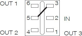
Pin Configuration and Descriptions
The SP3T switch has four terminals: one common terminal (COM) and three selectable output terminals (T1, T2, T3). The pin configuration is as follows:
| Pin | Label | Description |
|---|---|---|
| 1 | COM | Common terminal (input) |
| 2 | T1 | Output terminal 1 |
| 3 | T2 | Output terminal 2 |
| 4 | T3 | Output terminal 3 |
Usage Instructions
How to Use the SP3T Switch in a Circuit
- Identify the Terminals: Locate the COM terminal (input) and the three output terminals (T1, T2, T3).
- Connect the Input: Attach the input signal or power source to the COM terminal.
- Connect the Outputs: Connect the desired output circuits to T1, T2, and T3.
- Switch Operation: Manually toggle the switch to select the desired output path. The switch will connect the COM terminal to one of the three outputs (T1, T2, or T3) at a time.
Important Considerations and Best Practices
- Voltage and Current Ratings: Ensure the voltage and current applied to the switch do not exceed the specified ratings (0.5A at 125VAC or 0.3A at 250VAC).
- Debouncing: If used in digital circuits, consider implementing debouncing techniques to avoid erratic behavior when switching.
- Mounting: Securely mount the switch to a panel or enclosure to prevent mechanical stress on the terminals.
- Wiring: Use appropriate wire gauges and ensure secure connections to avoid loose contacts.
Example: Connecting to an Arduino UNO
The SP3T switch can be used with an Arduino UNO to select between three different inputs (e.g., sensors or signals). Below is an example code snippet:
// Define the pins connected to the SP3T switch outputs
const int switchPin1 = 2; // Connected to T1
const int switchPin2 = 3; // Connected to T2
const int switchPin3 = 4; // Connected to T3

void setup() {
  // Set the switch pins as input
  pinMode(switchPin1, INPUT);
  pinMode(switchPin2, INPUT);
  pinMode(switchPin3, INPUT);

  // Initialize serial communication for debugging
  Serial.begin(9600);
}

void loop() {
  // Read the state of each switch output
  bool state1 = digitalRead(switchPin1);
  bool state2 = digitalRead(switchPin2);
  bool state3 = digitalRead(switchPin3);

  // Print the active switch state to the Serial Monitor
  if (state1) {
    Serial.println("Switch is connected to T1");
  } else if (state2) {
    Serial.println("Switch is connected to T2");
  } else if (state3) {
    Serial.println("Switch is connected to T3");
  } else {
    Serial.println("No connection detected");
  }

  delay(500); // Add a small delay for stability
}
Troubleshooting and FAQs
Common Issues
No Output Signal:
- Cause: Loose or incorrect wiring.
- Solution: Verify all connections and ensure the input is connected to the COM terminal.
Intermittent Connection:
- Cause: Worn-out switch contacts or mechanical stress.
- Solution: Replace the switch if worn out. Ensure proper mounting to avoid stress.
Signal Noise or Flickering:
- Cause: Contact bounce when switching.
- Solution: Use a capacitor or software debouncing techniques in digital circuits.
Overheating:
- Cause: Exceeding the current or voltage ratings.
- Solution: Ensure the load does not exceed the specified ratings.
FAQs
Q: Can the SP3T switch handle DC signals?
A: Yes, the switch can handle DC signals as long as the voltage and current ratings are not exceeded.Q: Can I use the SP3T switch for audio applications?
A: Yes, the switch is suitable for low-power audio signal routing.Q: How do I clean the switch contacts?
A: Use a contact cleaner spray to remove dirt or oxidation from the contacts.Q: Can I automate the switching process?
A: No, the Salecom T812 is a manual switch. For automated switching, consider using relays or electronic switches.
This concludes the documentation for the Salecom T812 SP3T switch.