How to Use AD7607 Eval: Examples, Pinouts, and Specs
Introduction
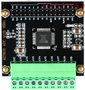
The AD7607 Eval is an evaluation board designed for the AD7607, a high-performance 16-bit, 8-channel, simultaneous sampling analog-to-digital converter (ADC). This board simplifies the process of testing and evaluating the AD7607's capabilities, making it an essential tool for engineers and developers working on precision data acquisition systems. The AD7607 Eval provides easy access to the ADC's features, including its wide input voltage range, high-speed sampling, and integrated signal conditioning.
Explore Projects Built with AD7607 Eval


Explore Projects Built with AD7607 Eval
Common Applications and Use Cases
- Data acquisition systems
- Industrial process control
- Power quality monitoring
- Medical instrumentation
- Vibration analysis and condition monitoring
Technical Specifications
Key Technical Details
- ADC Resolution: 16 bits
- Number of Channels: 8 (simultaneous sampling)
- Input Voltage Range: ±10 V, ±5 V (software-selectable)
- Sampling Rate: Up to 200 kSPS per channel
- Power Supply: +5 V (AVCC), ±12 V (optional for input buffers)
- Communication Interface: Parallel or Serial (SPI-compatible)
- Operating Temperature Range: -40°C to +85°C
- Onboard Features: Input buffers, reference voltage, and configurable jumpers
Pin Configuration and Descriptions
The AD7607 Eval board provides multiple connectors and pins for interfacing with external systems. Below is a summary of the key pin configurations:
Power Supply Pins
| Pin Name | Description | Voltage Level |
|---|---|---|
| AVCC | Analog supply voltage input | +5 V |
| DVCC | Digital supply voltage input | +3.3 V or +5 V |
| AGND | Analog ground | 0 V |
| DGND | Digital ground | 0 V |
| V±12 | Optional ±12 V for input buffers | ±12 V |
Signal Input Pins
| Pin Name | Description | Notes |
|---|---|---|
| CH1 to CH8 | Analog input channels 1 to 8 | Accepts ±10 V or ±5 V signals |
| REF | Reference voltage input/output | Default: 2.5 V |
Communication Interface Pins
| Pin Name | Description | Notes |
|---|---|---|
| CS | Chip select | Active low |
| RD | Read data | Active low |
| WR | Write data | Active low |
| DB[0:15] | Parallel data bus (16 bits) | For parallel communication |
| SCLK | Serial clock | For SPI communication |
| DIN | Serial data input | For SPI communication |
| DOUT | Serial data output | For SPI communication |
Usage Instructions
How to Use the AD7607 Eval in a Circuit
Power Supply Setup:
- Connect +5 V to the AVCC pin and ground to AGND.
- If using the input buffers, provide ±12 V to the V±12 pins.
- Ensure the DVCC pin is supplied with +3.3 V or +5 V, depending on the logic level of your system.
Input Signal Configuration:
- Connect the analog input signals to CH1 through CH8.
- Use the onboard jumpers to select the desired input voltage range (±10 V or ±5 V).
Communication Interface:
- For parallel communication, connect the DB[0:15] pins to your microcontroller or FPGA.
- For SPI communication, connect SCLK, DIN, DOUT, and CS to the corresponding pins on your microcontroller.
Data Acquisition:
- Use the RD and WR pins (for parallel mode) or the SCLK and CS pins (for SPI mode) to control data transfer.
- Read the converted digital data from the output pins.
Software Configuration:
- Configure the ADC settings (e.g., input range, sampling rate) using the onboard jumpers or external control signals.
Important Considerations and Best Practices
- Ensure proper grounding between the AD7607 Eval board and your external system to minimize noise.
- Use decoupling capacitors on the power supply lines to reduce power supply noise.
- Avoid exceeding the specified input voltage range to prevent damage to the ADC.
- For SPI communication, ensure the clock frequency does not exceed the ADC's maximum supported rate.
Example Code for Arduino UNO (SPI Mode)
Below is an example of how to interface the AD7607 Eval with an Arduino UNO using SPI:
#include <SPI.h>

// Pin definitions
const int CS_PIN = 10;  // Chip select pin
const int RDY_PIN = 9;  // Ready pin (optional, if used)

// Setup function
void setup() {
  pinMode(CS_PIN, OUTPUT);
  pinMode(RDY_PIN, INPUT);
  digitalWrite(CS_PIN, HIGH);  // Set CS high (inactive)

  // Initialize SPI
  SPI.begin();
  SPI.setClockDivider(SPI_CLOCK_DIV16);  // Set SPI clock speed
  SPI.setDataMode(SPI_MODE1);            // SPI mode 1
  SPI.setBitOrder(MSBFIRST);             // MSB first
  Serial.begin(9600);                    // Initialize serial communication
}

// Function to read data from AD7607
uint16_t readADC() {
  digitalWrite(CS_PIN, LOW);  // Select the ADC
  delayMicroseconds(1);       // Small delay for setup

  // Read 16-bit data (2 bytes)
  uint8_t highByte = SPI.transfer(0x00);  // Send dummy byte, receive high byte
  uint8_t lowByte = SPI.transfer(0x00);   // Send dummy byte, receive low byte

  digitalWrite(CS_PIN, HIGH);  // Deselect the ADC

  // Combine high and low bytes into a 16-bit value
  return (highByte << 8) | lowByte;
}

void loop() {
  if (digitalRead(RDY_PIN) == LOW) {  // Check if data is ready
    uint16_t adcValue = readADC();    // Read ADC value
    Serial.println(adcValue);         // Print ADC value to serial monitor
  }
}
Troubleshooting and FAQs
Common Issues and Solutions
No Output Data:
- Ensure the power supply connections are correct and stable.
- Verify that the communication interface (parallel or SPI) is properly configured.
Incorrect ADC Values:
- Check the input signal levels to ensure they are within the selected range (±10 V or ±5 V).
- Verify the reference voltage is stable and within the specified range.
Communication Errors:
- For SPI mode, ensure the clock frequency and SPI mode settings match the ADC's requirements.
- Check for loose or incorrect connections on the communication pins.
Excessive Noise in Output:
- Use proper grounding and shielding techniques to minimize noise.
- Add decoupling capacitors to the power supply lines.
FAQs
Q: Can I use the AD7607 Eval with a 3.3 V microcontroller?
A: Yes, the AD7607 Eval supports a DVCC voltage of 3.3 V, making it compatible with 3.3 V logic systems.
Q: How do I select the input voltage range?
A: Use the onboard jumpers to configure the input voltage range to either ±10 V or ±5 V.
Q: What is the maximum sampling rate of the AD7607?
A: The AD7607 supports a maximum sampling rate of 200 kSPS per channel.
Q: Can I use the AD7607 Eval without the input buffers?
A: Yes, the input buffers are optional and can be bypassed if not required for your application.