How to Use Touch Sensor With Led: Examples, Pinouts, and Specs
Introduction
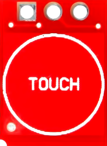
The Touch Sensor with LED is an electronic component designed to detect touch input and provide immediate visual feedback through an integrated LED. This component is widely used in interactive applications, user interfaces, and touch-based control systems. Its compact design and ease of use make it ideal for projects requiring touch-sensitive functionality, such as home automation, wearable devices, and educational projects.
Explore Projects Built with Touch Sensor With Led
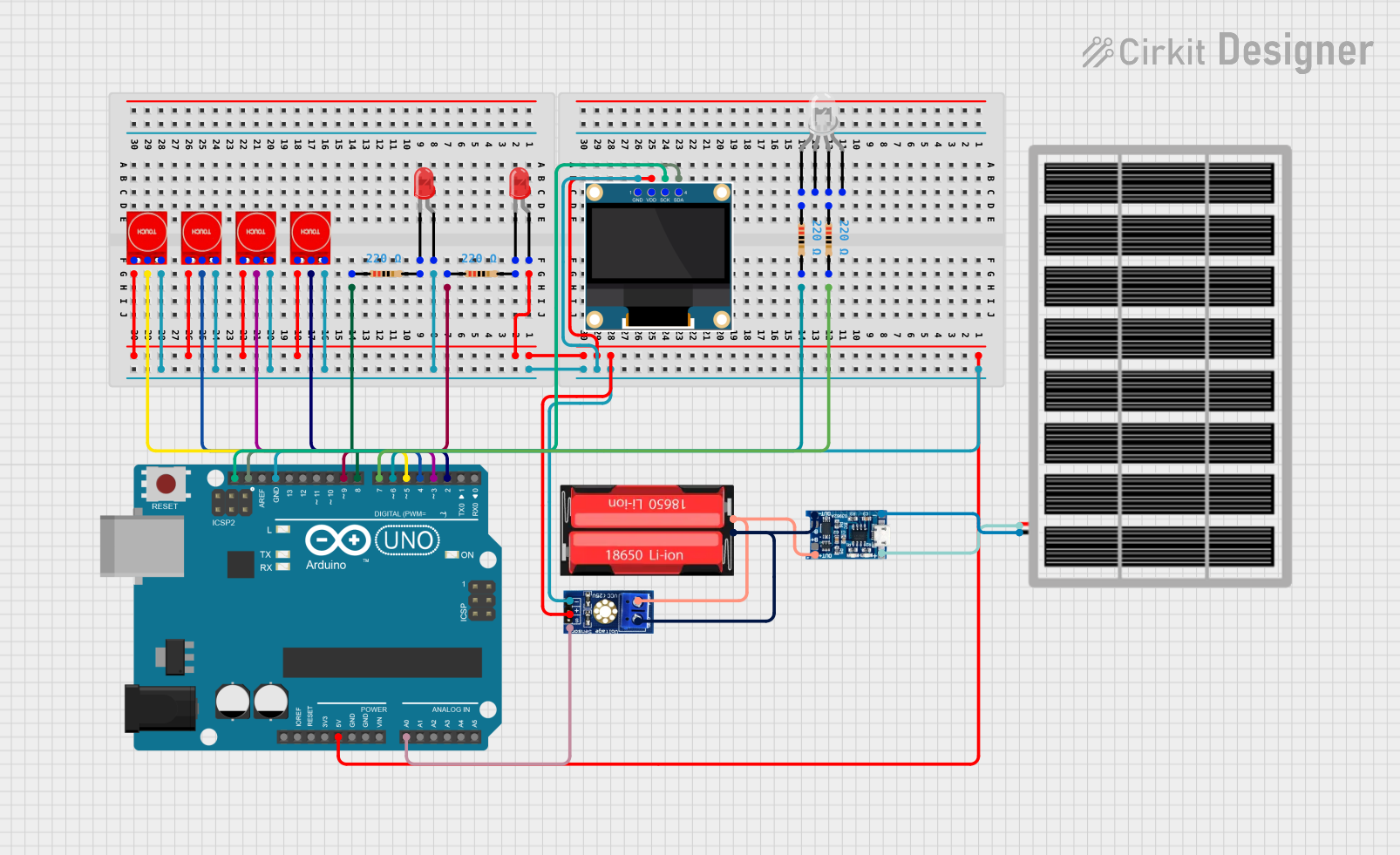
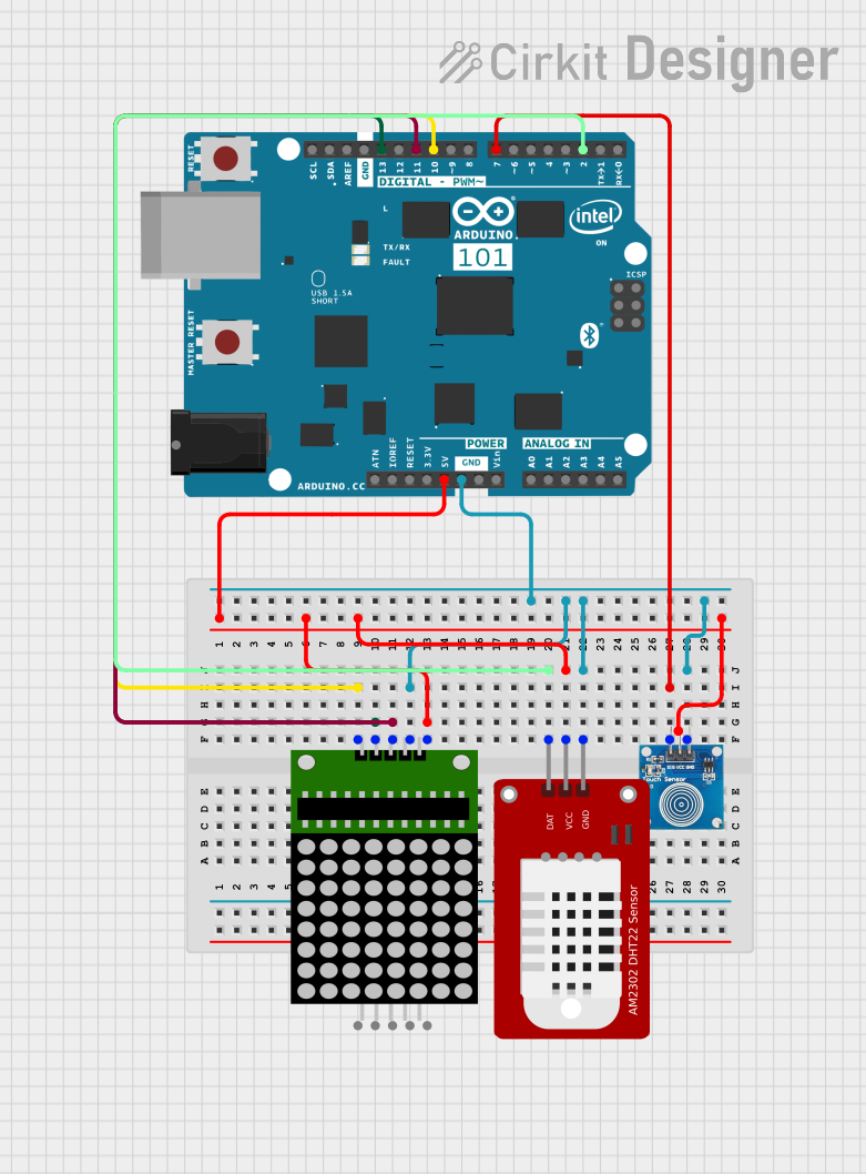
Explore Projects Built with Touch Sensor With Led
Technical Specifications
- Operating Voltage: 2.7V to 6V
- Operating Current: < 10mA
- Touch Sensitivity: Capacitive touch detection
- Output Type: Digital (High/Low)
- Integrated LED: Provides visual feedback when touch is detected
- Response Time: < 60ms
- Operating Temperature: -20°C to 70°C
- Dimensions: Typically 10mm x 10mm (varies by manufacturer)
Pin Configuration and Descriptions
| Pin | Name | Description |
|---|---|---|
| 1 | VCC | Power supply input (2.7V to 6V). Connect to the positive terminal of the power source. |
| 2 | GND | Ground. Connect to the negative terminal of the power source. |
| 3 | OUT | Digital output pin. Outputs HIGH when touch is detected, LOW otherwise. |
Usage Instructions
How to Use the Component in a Circuit
- Power the Sensor: Connect the
VCCpin to a 3.3V or 5V power source (depending on your system) and theGNDpin to ground. - Connect the Output: Attach the
OUTpin to a microcontroller input pin (e.g., Arduino) or directly to another circuit element that requires a digital signal. - Observe the LED: The integrated LED will light up when the sensor detects a touch, providing immediate visual feedback.
Important Considerations and Best Practices
- Debouncing: The sensor may produce noise or false triggers. Use software debouncing in your microcontroller code to ensure stable readings.
- Power Supply: Ensure a stable power supply to avoid erratic behavior.
- Placement: Avoid placing the sensor near high-frequency noise sources or conductive materials that may interfere with touch detection.
- Touch Surface: For optimal performance, ensure the touch surface is clean and free of moisture or debris.
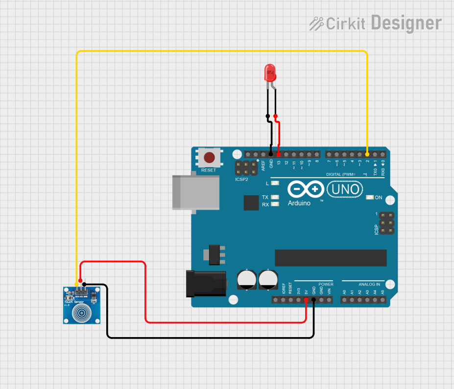
Example: Connecting to an Arduino UNO
Below is an example of how to connect and use the Touch Sensor with LED with an Arduino UNO:
Circuit Connections
- Connect the
VCCpin of the sensor to the 5V pin on the Arduino. - Connect the
GNDpin of the sensor to the GND pin on the Arduino. - Connect the
OUTpin of the sensor to digital pin 2 on the Arduino.
Arduino Code
// Define the pin connected to the sensor's OUT pin
const int touchSensorPin = 2;

// Define the pin for the onboard LED (optional visual feedback)
const int ledPin = 13;

void setup() {
  // Initialize the touch sensor pin as input
  pinMode(touchSensorPin, INPUT);

  // Initialize the onboard LED pin as output
  pinMode(ledPin, OUTPUT);

  // Start the serial communication for debugging
  Serial.begin(9600);
}

void loop() {
  // Read the state of the touch sensor
  int touchState = digitalRead(touchSensorPin);

  // Print the touch state to the Serial Monitor
  Serial.println(touchState);

  // If touch is detected, turn on the LED
  if (touchState == HIGH) {
    digitalWrite(ledPin, HIGH); // Turn on the LED
  } else {
    digitalWrite(ledPin, LOW);  // Turn off the LED
  }

  // Add a small delay to stabilize readings
  delay(50);
}
Troubleshooting and FAQs
Common Issues and Solutions
The LED Does Not Light Up When Touched
- Ensure the
VCCandGNDpins are connected correctly. - Verify that the power supply voltage is within the specified range (2.7V to 6V).
- Check for loose or faulty connections in the circuit.
- Ensure the
False Triggers or Unstable Output
- Use a stable power source to minimize noise.
- Implement software debouncing in your microcontroller code to filter out noise.
- Avoid placing the sensor near high-frequency noise sources or conductive materials.
Touch Sensor Not Responding
- Ensure the touch surface is clean and free of moisture or debris.
- Verify that the
OUTpin is properly connected to the microcontroller or circuit.
FAQs
Q: Can I use this sensor with a 3.3V system?
A: Yes, the sensor operates within a voltage range of 2.7V to 6V, making it compatible with both 3.3V and 5V systems.
Q: Can I extend the touch surface?
A: Yes, you can attach a conductive material (e.g., aluminum foil) to the touch surface to increase its size. However, ensure the material is securely connected and does not introduce noise.
Q: Is the sensor waterproof?
A: No, the sensor is not waterproof. Avoid exposing it to moisture or liquids to prevent damage.
Q: Can I use multiple sensors in the same project?
A: Yes, you can use multiple sensors by connecting their OUT pins to different input pins on your microcontroller. Ensure each sensor has a stable power supply.