
How to Use pb emergency: Examples, Pinouts, and Specs
 Design with pb emergency in Cirkit Designer
Introduction
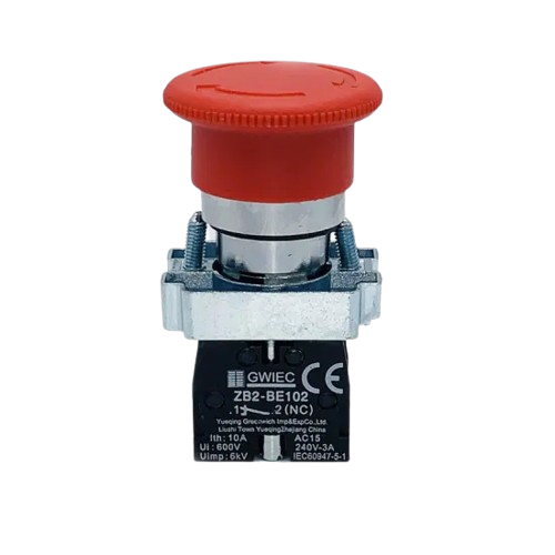
The PB Emergency is a push button switch specifically designed for emergency situations. It allows users to quickly interrupt power or activate safety mechanisms in a circuit, ensuring safety and control in critical scenarios. This component is commonly used in industrial machinery, safety systems, and emergency stop circuits.
Explore Projects Built with pb emergency
 Open Project in Cirkit Designer
 Open Project in Cirkit Designer
 Open Project in Cirkit Designer
 Open Project in Cirkit Designer
Explore Projects Built with pb emergency
Open Project in Cirkit DesignerOpen Project in Cirkit DesignerOpen Project in Cirkit DesignerOpen Project in Cirkit DesignerCommon Applications
- Emergency stop mechanisms in industrial equipment
- Safety circuits in automation systems
- Power interruption in hazardous environments
- Reset or override controls in critical systems
Technical Specifications
Key Technical Details
| Parameter | Value |
|---|---|
| Manufacturer | [Insert Manufacturer Name] |
| Manufacturer Part ID | [Insert Manufacturer Part ID] |
| Switch Type | Momentary Push Button |
| Contact Configuration | Normally Open (NO) or Normally Closed (NC) |
| Operating Voltage | 12V - 250V AC/DC |
| Maximum Current Rating | 10A |
| Actuation Force | 2.5N |
| Mechanical Durability | 1,000,000 cycles |
| Mounting Style | Panel Mount |
| Operating Temperature | -25°C to +70°C |
| Terminal Type | Screw Terminals |
| Button Color | Red (standard for emergency use) |
Pin Configuration and Descriptions
The PB Emergency switch typically has two or four terminals, depending on the contact configuration (NO or NC). Below is the pin description:
| Pin Number | Label | Description |
|---|---|---|
| 1 | NO | Normally Open contact |
| 2 | COM | Common terminal |
| 3 (optional) | NC | Normally Closed contact (if present) |
| 4 (optional) | COM | Common terminal (if present) |
Usage Instructions
How to Use the PB Emergency in a Circuit
- Determine the Contact Configuration: Identify whether the switch is configured as Normally Open (NO) or Normally Closed (NC). This will dictate how the switch behaves when pressed.
- Connect the Terminals:
- For NO configuration: Connect one wire to the NO terminal and the other to the COM terminal. The circuit will close when the button is pressed.
- For NC configuration: Connect one wire to the NC terminal and the other to the COM terminal. The circuit will open when the button is pressed.
- Mount the Switch: Secure the PB Emergency switch to a panel or enclosure using the provided mounting hardware.
- Test the Circuit: Verify that the switch operates as intended by pressing the button and observing the circuit's behavior.
Important Considerations and Best Practices
- Voltage and Current Ratings: Ensure the switch is used within its specified voltage and current ratings to avoid damage or failure.
- Wiring: Use appropriately rated wires and ensure secure connections to the terminals.
- Environment: Avoid exposing the switch to extreme temperatures, moisture, or corrosive environments unless it is specifically rated for such conditions.
- Safety Compliance: When used in safety-critical applications, ensure the switch complies with relevant safety standards and regulations.
Example: Connecting PB Emergency to an Arduino UNO
The PB Emergency switch can be used with an Arduino UNO to trigger an emergency stop or reset function. Below is an example circuit and code:
Circuit Diagram
- Connect the NO terminal of the PB Emergency switch to Arduino digital pin 2.
- Connect the COM terminal to the Arduino GND pin.
- Use a pull-up resistor (10kΩ) between digital pin 2 and 5V to ensure a stable signal.
Arduino Code
// Define the pin connected to the PB Emergency switch
const int emergencyButtonPin = 2;

// Variable to store the button state
int buttonState = HIGH;

void setup() {
  // Set the button pin as input with pull-up resistor
  pinMode(emergencyButtonPin, INPUT_PULLUP);

  // Initialize serial communication for debugging
  Serial.begin(9600);
}

void loop() {
  // Read the state of the button
  buttonState = digitalRead(emergencyButtonPin);

  // Check if the button is pressed
  if (buttonState == LOW) {
    // Button is pressed, trigger emergency action
    Serial.println("Emergency button pressed! Taking action...");
    // Add your emergency handling code here
  } else {
    // Button is not pressed
    Serial.println("System running normally.");
  }

  // Small delay to debounce the button
  delay(50);
}
Troubleshooting and FAQs
Common Issues and Solutions
| Issue | Possible Cause | Solution |
|---|---|---|
| Switch does not activate the circuit | Loose or incorrect wiring | Verify all connections and tighten screws. |
| Button feels stuck or unresponsive | Mechanical wear or debris | Inspect and clean the button mechanism. |
| Circuit behaves erratically | Missing or incorrect pull-up resistor | Add or verify the pull-up resistor in the circuit. |
| Switch overheats | Exceeding voltage or current ratings | Ensure the switch is used within its specified ratings. |
FAQs
Can the PB Emergency switch be used outdoors?
- Only if it is rated for outdoor use or installed in a weatherproof enclosure.
What is the difference between NO and NC configurations?
- NO (Normally Open): The circuit is open by default and closes when the button is pressed.
- NC (Normally Closed): The circuit is closed by default and opens when the button is pressed.
How do I replace a damaged PB Emergency switch?
- Disconnect power, remove the damaged switch, and install a new one following the wiring and mounting instructions.
Can I use the PB Emergency switch with low-voltage circuits?
- Yes, as long as the voltage and current are within the switch's specified range.
By following this documentation, users can effectively integrate the PB Emergency switch into their circuits and ensure reliable operation in emergency scenarios.