
How to Use JST VH VHR-3N 3-Circuit Receptacle Housing: Examples, Pinouts, and Specs
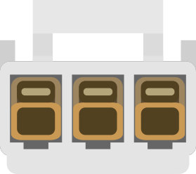
 Design with JST VH VHR-3N 3-Circuit Receptacle Housing in Cirkit Designer
Introduction
The JST VH VHR-3N is a compact and durable 3-circuit receptacle housing designed for use with JST VH series connectors. It provides a reliable and secure connection for electrical circuits, making it ideal for applications requiring robust and compact wiring solutions. This component is widely used in consumer electronics, industrial equipment, and automotive systems due to its high reliability and ease of use.
Explore Projects Built with JST VH VHR-3N 3-Circuit Receptacle Housing
 Open Project in Cirkit Designer
 Open Project in Cirkit Designer
 Open Project in Cirkit Designer
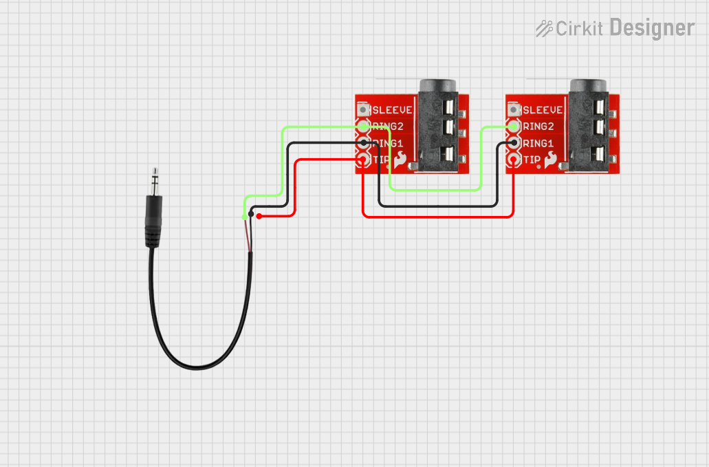 Open Project in Cirkit Designer
Explore Projects Built with JST VH VHR-3N 3-Circuit Receptacle Housing
Open Project in Cirkit DesignerOpen Project in Cirkit DesignerOpen Project in Cirkit DesignerOpen Project in Cirkit DesignerCommon Applications
- Consumer electronics (e.g., power supplies, appliances)
- Industrial control systems
- Automotive wiring harnesses
- LED lighting systems
- Battery connections
Technical Specifications
The JST VH VHR-3N is designed to meet the needs of high-current and high-density applications. Below are its key technical details:
Key Specifications
| Parameter | Value |
|---|---|
| Manufacturer | JST |
| Part Number | VHR-3N |
| Number of Circuits | 3 |
| Housing Material | Nylon 66 (UL94V-0, flame-retardant) |
| Operating Temperature | -25°C to +85°C |
| Voltage Rating | 250V AC/DC |
| Current Rating | 10A |
| Wire Gauge Compatibility | 18-22 AWG |
| Mating Connector | JST VH series headers |
Pin Configuration and Descriptions
The VHR-3N housing accommodates three circuits, each corresponding to a pin in the mating connector. Below is the pin configuration:
| Pin Number | Description | Notes |
|---|---|---|
| 1 | Circuit 1 (Positive/Signal) | Connect to the first wire or signal line |
| 2 | Circuit 2 (Ground/Signal) | Connect to the second wire or signal line |
| 3 | Circuit 3 (Negative/Signal) | Connect to the third wire or signal line |
Usage Instructions
How to Use the JST VH VHR-3N in a Circuit
- Prepare the Wires: Strip the insulation from the wires to expose approximately 3-5mm of conductor. Ensure the wire gauge is between 18-22 AWG for compatibility.
- Crimp the Contacts: Use JST's recommended crimping tool to attach the crimp terminals (e.g., JST SVH-21T-P1.1) to the stripped wires. Ensure a secure and proper crimp for reliable connections.
- Insert the Contacts: Insert the crimped terminals into the VHR-3N housing until they click into place. Verify that the terminals are fully seated and locked.
- Connect to the Mating Header: Align the VHR-3N housing with the mating JST VH series header and push it in until it locks securely.
Important Considerations and Best Practices
- Wire Selection: Use wires within the specified gauge range (18-22 AWG) to ensure proper fit and electrical performance.
- Crimping Tool: Always use the recommended crimping tool to achieve consistent and reliable crimps.
- Insertion Check: After inserting the terminals into the housing, gently pull on the wires to confirm they are securely locked.
- Mating and Unmating: Avoid excessive force when mating or unmating the connector to prevent damage to the housing or terminals.
- Environmental Conditions: Ensure the operating environment is within the specified temperature range (-25°C to +85°C) and avoid exposure to harsh chemicals or moisture.
Example: Connecting to an Arduino UNO
The JST VH VHR-3N can be used to connect power or signals to an Arduino UNO. Below is an example of wiring a 12V power supply to an Arduino UNO using the VHR-3N:
- Connect the 12V positive wire to Pin 1 of the VHR-3N.
- Connect the ground wire to Pin 2 of the VHR-3N.
- Use a mating JST VH series header to connect the VHR-3N to the Arduino's power input.
// Example Arduino code for reading a signal connected via the VHR-3N
const int signalPin = 2; // Pin connected to Circuit 1 of the VHR-3N

void setup() {
  pinMode(signalPin, INPUT); // Set the signal pin as input
  Serial.begin(9600);        // Initialize serial communication
}

void loop() {
  int signalValue = digitalRead(signalPin); // Read the signal value
  Serial.print("Signal Value: ");
  Serial.println(signalValue); // Print the signal value to the serial monitor
  delay(500);                  // Wait for 500ms before reading again
}
Troubleshooting and FAQs
Common Issues and Solutions
| Issue | Possible Cause | Solution |
|---|---|---|
| Terminals not locking in place | Improper crimping or incorrect terminal | Ensure proper crimping and use the correct terminal type (e.g., SVH-21T-P1.1). |
| Loose connection | Terminals not fully seated | Push the terminals until they click into place. |
| Connector does not mate | Misalignment or incompatible header | Verify alignment and ensure the mating header is a JST VH series connector. |
| Overheating during operation | Exceeding current rating | Ensure the current does not exceed 10A. Use thicker wires if necessary. |
FAQs
Q: Can I use this housing with wires outside the 18-22 AWG range?
A: No, using wires outside the specified range may result in poor connections or damage to the housing.
Q: What crimping tool should I use?
A: Use JST's recommended crimping tool, such as the YC-160R, for consistent and reliable crimps.
Q: Is the VHR-3N suitable for outdoor use?
A: The VHR-3N is not specifically designed for outdoor use. If used outdoors, ensure it is protected from moisture and extreme environmental conditions.
Q: Can I reuse the housing after removing the terminals?
A: Yes, the housing can be reused if the terminals are carefully removed without damaging the locking mechanism. Use a terminal removal tool for best results.