How to Use DC DC converter: Examples, Pinouts, and Specs
Introduction
A DC DC converter is an electronic circuit that converts a direct current (DC) voltage from one level to another. It is widely used for voltage regulation and power management in various applications, such as portable electronics, automotive systems, renewable energy systems, and industrial equipment. By efficiently stepping up or stepping down voltage levels, DC DC converters ensure that electronic devices receive the appropriate power supply for optimal performance.
Common applications and use cases include:
- Powering microcontrollers and sensors in embedded systems.
- Voltage regulation in battery-powered devices.
- Energy conversion in solar power systems.
- Supplying stable voltage to automotive electronics.
- Boosting or bucking voltage in industrial power supplies.
Explore Projects Built with DC DC converter


Explore Projects Built with DC DC converter
Technical Specifications
Below are the general technical specifications for a typical DC DC converter. Note that specific values may vary depending on the model and manufacturer.
Key Technical Details
- Input Voltage Range: 3V to 40V (varies by model)
- Output Voltage Range: 1.2V to 35V (adjustable in many models)
- Output Current: Up to 3A (depending on the design)
- Efficiency: Up to 95% (varies with load and input/output conditions)
- Switching Frequency: 150 kHz to 1 MHz
- Operating Temperature: -40°C to +85°C
- Protection Features: Overcurrent protection, thermal shutdown, and short-circuit protection.
Pin Configuration and Descriptions
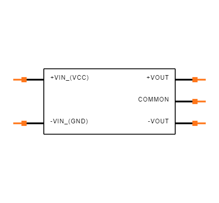
The pin configuration of a DC DC converter depends on its type (e.g., buck, boost, or buck-boost) and package. Below is an example pinout for a common adjustable buck converter module (e.g., LM2596-based module):
| Pin Name | Description |
|---|---|
| VIN | Input voltage pin. Connect the DC input voltage source here. |
| GND | Ground pin. Connect to the ground of the input and output circuits. |
| VOUT | Output voltage pin. Provides the regulated DC output voltage. |
| ADJ (or FB) | Adjustment or feedback pin. Used to set the output voltage (via a potentiometer or resistor). |
Usage Instructions
How to Use the Component in a Circuit
- Connect the Input Voltage:
- Attach the positive terminal of the DC power source to the
VINpin. - Connect the negative terminal of the power source to the
GNDpin.
- Attach the positive terminal of the DC power source to the
- Set the Output Voltage:
- If the module has an adjustable output, use the onboard potentiometer to set the desired output voltage.
- Alternatively, use external resistors to configure the output voltage (refer to the datasheet for resistor values).
- Connect the Load:
- Attach the positive terminal of the load to the
VOUTpin. - Connect the negative terminal of the load to the
GNDpin.
- Attach the positive terminal of the load to the
- Power On:
- Turn on the input power source and measure the output voltage to ensure it matches the desired value before connecting sensitive devices.
Important Considerations and Best Practices
- Input Voltage Range: Ensure the input voltage is within the specified range of the converter to avoid damage.
- Heat Dissipation: For high-current applications, use a heatsink or ensure proper ventilation to prevent overheating.
- Output Capacitors: Use appropriate capacitors at the output to stabilize the voltage and reduce noise.
- Load Requirements: Verify that the converter can supply sufficient current for your load.
- Polarity: Double-check the polarity of connections to avoid damaging the module.
Example: Using a DC DC Converter with Arduino UNO
Below is an example of how to use a DC DC converter to power an Arduino UNO from a 12V battery:
- Connect the 12V battery to the
VINandGNDpins of the DC DC converter. - Adjust the output voltage of the converter to 5V using the potentiometer.
- Connect the
VOUTpin of the converter to the5Vpin of the Arduino UNO. - Connect the
GNDpin of the converter to theGNDpin of the Arduino UNO.
// Example Arduino code to blink an LED when powered by a DC DC converter

const int ledPin = 13; // Pin connected to the onboard LED

void setup() {
  pinMode(ledPin, OUTPUT); // Set the LED pin as an output
}

void loop() {
  digitalWrite(ledPin, HIGH); // Turn the LED on
  delay(1000);                // Wait for 1 second
  digitalWrite(ledPin, LOW);  // Turn the LED off
  delay(1000);                // Wait for 1 second
}
Troubleshooting and FAQs
Common Issues and Solutions
No Output Voltage:
- Cause: Incorrect input voltage or loose connections.
- Solution: Verify the input voltage is within the specified range and check all connections.
Output Voltage is Unstable:
- Cause: Insufficient output capacitors or high load current.
- Solution: Add appropriate capacitors to the output and ensure the load current is within the converter's limits.
Overheating:
- Cause: High current draw or poor ventilation.
- Solution: Use a heatsink or fan to improve heat dissipation.
Output Voltage Does Not Match the Set Value:
- Cause: Incorrect adjustment of the potentiometer or damaged module.
- Solution: Re-adjust the potentiometer or replace the module if necessary.
FAQs
Q: Can I use a DC DC converter to power sensitive electronics?
A: Yes, but ensure the output voltage is stable and within the tolerance range of your device. Adding capacitors can help reduce noise.Q: What is the difference between a buck and a boost converter?
A: A buck converter steps down the input voltage, while a boost converter steps up the input voltage.Q: Can I use a DC DC converter with an AC power source?
A: No, DC DC converters are designed for DC input only. Use an AC to DC adapter to convert AC to DC first.Q: How do I calculate the efficiency of a DC DC converter?
A: Efficiency (%) = (Output Power / Input Power) × 100. Measure the input and output voltages and currents to calculate power.
By following this documentation, you can effectively use a DC DC converter in your projects and troubleshoot common issues.