How to Use rectifier ac to dc: Examples, Pinouts, and Specs
Introduction
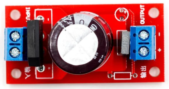
A rectifier is an essential electronic component that converts alternating current (AC) to direct current (DC). This conversion is crucial in many electronic devices and systems, as most electronic circuits require a stable DC supply to operate correctly. Rectifiers are commonly used in power supplies, battery charging systems, and various electronic devices.
Explore Projects Built with rectifier ac to dc


Explore Projects Built with rectifier ac to dc
Common Applications and Use Cases
- Power Supplies: Rectifiers are used in power supply units to convert AC from the mains to DC for electronic devices.
- Battery Chargers: They are used in battery chargers to convert AC to DC for charging batteries.
- Radio Signal Detection: Rectifiers are used in radio receivers to demodulate amplitude-modulated (AM) signals.
- DC Motor Drives: They are used in DC motor drives to provide the necessary DC voltage.
Technical Specifications
Key Technical Details
| Parameter | Value |
|---|---|
| Input Voltage | 110V - 240V AC |
| Output Voltage | 5V - 24V DC |
| Maximum Current | 1A - 10A |
| Power Rating | 5W - 240W |
| Efficiency | 80% - 95% |
| Ripple Voltage | < 1% of output voltage |
| Operating Temperature | -40°C to 85°C |
Pin Configuration and Descriptions
| Pin Number | Pin Name | Description |
|---|---|---|
| 1 | AC In 1 | First AC input terminal |
| 2 | AC In 2 | Second AC input terminal |
| 3 | DC Out + | Positive DC output terminal |
| 4 | DC Out - | Negative DC output terminal (Ground) |
Usage Instructions
How to Use the Component in a Circuit
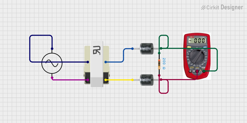
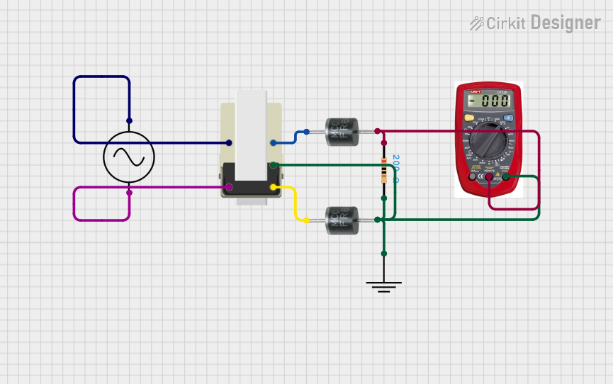
Connect the AC Input:
- Connect the AC In 1 and AC In 2 pins to the AC source. Ensure the voltage rating of the rectifier matches the AC source voltage.
Connect the DC Output:
- Connect the DC Out + pin to the positive terminal of the load.
- Connect the DC Out - pin to the negative terminal (ground) of the load.
Filtering (Optional):
- To reduce ripple voltage, connect a capacitor across the DC output terminals. The value of the capacitor depends on the desired ripple voltage and load current.
Important Considerations and Best Practices
- Heat Dissipation: Ensure proper heat dissipation by using heat sinks or cooling fans if the rectifier operates at high currents.
- Voltage Rating: Always check the voltage rating of the rectifier to prevent damage from overvoltage.
- Polarity: Ensure correct polarity when connecting the DC output to avoid damaging the load.
- Safety: Handle AC connections with care to avoid electric shock. Use insulated tools and follow safety guidelines.
Troubleshooting and FAQs
Common Issues Users Might Face
No DC Output:
- Solution: Check the AC input connections and ensure the AC source is functioning. Verify the rectifier's voltage rating matches the AC source voltage.
High Ripple Voltage:
- Solution: Add a filtering capacitor across the DC output terminals. Ensure the capacitor value is appropriate for the load current.
Overheating:
- Solution: Ensure proper heat dissipation using heat sinks or cooling fans. Check for excessive load current and reduce if necessary.
Incorrect Output Voltage:
- Solution: Verify the AC input voltage and ensure it matches the rectifier's specifications. Check for any loose connections.
FAQs
Q1: Can I use a rectifier with an Arduino UNO?
- A1: Yes, you can use a rectifier to convert AC to DC and then use the DC output to power the Arduino UNO. Ensure the output voltage matches the Arduino's input voltage requirements (typically 5V or 9V).
Q2: What type of capacitor should I use for filtering?
- A2: Use an electrolytic capacitor with a voltage rating higher than the rectifier's output voltage. The capacitance value depends on the desired ripple voltage and load current.
Q3: Can I use a rectifier for high-frequency AC signals?
- A3: Standard rectifiers are designed for low-frequency AC (50Hz/60Hz). For high-frequency AC signals, use specialized high-frequency rectifiers or diodes.
Q4: How do I calculate the required heat sink size?
- A4: Calculate the power dissipation (P = V * I) and use the thermal resistance (Rθ) of the heat sink to determine the required size. Ensure the junction temperature remains within safe limits.
By following this documentation, users can effectively utilize a rectifier to convert AC to DC in various applications, ensuring proper operation and longevity of their electronic devices.