How to Use st7735: Examples, Pinouts, and Specs
Introduction
The ST7735 is a low-power, full-color LCD driver manufactured by Arduino (Part ID: LCD). It is designed to support a variety of display resolutions, making it ideal for small displays in embedded systems. This component is widely used for rendering graphics and text in applications such as handheld devices, IoT projects, and portable instrumentation.
Explore Projects Built with st7735


Explore Projects Built with st7735
Common Applications and Use Cases
- Handheld gaming devices
- Wearable technology
- IoT dashboards and displays
- Portable measurement tools
- Educational and hobbyist projects
Technical Specifications
The ST7735 LCD driver is a versatile component with the following key specifications:
| Parameter | Value |
|---|---|
| Operating Voltage | 2.8V to 3.3V |
| Interface Type | SPI (Serial Peripheral Interface) |
| Display Colors | 65K (16-bit RGB) |
| Maximum Resolution | 132 x 162 pixels |
| Operating Temperature | -30°C to 85°C |
| Power Consumption | Low-power operation |
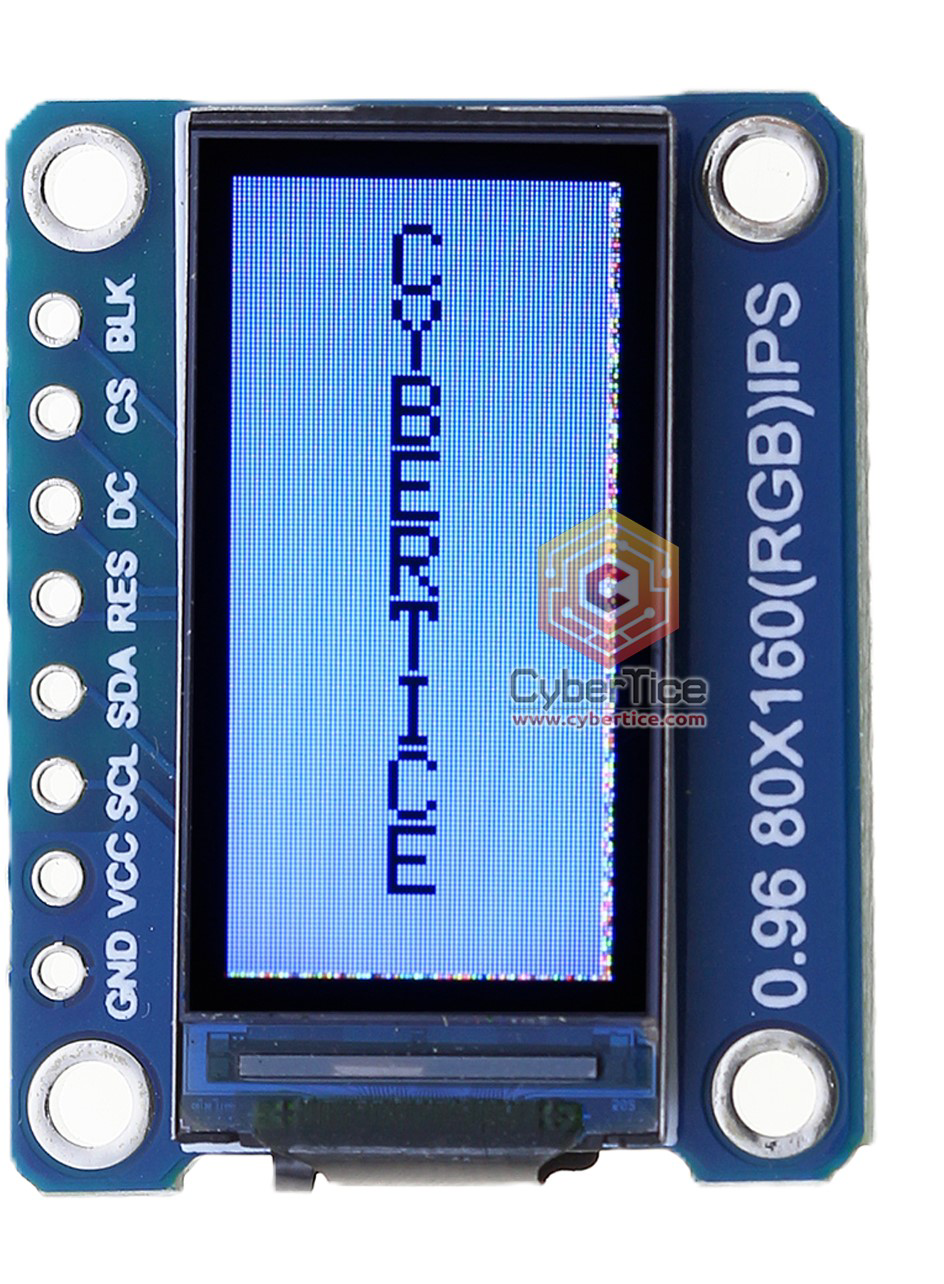
Pin Configuration and Descriptions
The ST7735 typically uses an SPI interface with the following pin configuration:
| Pin Name | Pin Number | Description |
|---|---|---|
| VCC | 1 | Power supply input (2.8V to 3.3V). |
| GND | 2 | Ground connection. |
| SCL | 3 | Serial clock input for SPI communication. |
| SDA | 4 | Serial data input/output for SPI communication. |
| RES | 5 | Reset pin. Active low; used to reset the display. |
| DC | 6 | Data/Command control pin. High for data, low for command. |
| CS | 7 | Chip select pin. Active low; enables communication with the display. |
| BLK | 8 | Backlight control pin. Connect to power or PWM for brightness control. |
Usage Instructions
The ST7735 can be easily integrated into a circuit using its SPI interface. Below are the steps and best practices for using the component:
Connecting the ST7735 to an Arduino UNO
- Power Supply: Connect the VCC pin to the 3.3V output of the Arduino UNO and the GND pin to ground.
- SPI Pins: Connect the SCL pin to Arduino's
D13(SCK) and the SDA pin toD11(MOSI). - Control Pins:
- Connect the RES pin to
D8. - Connect the DC pin to
D9. - Connect the CS pin to
D10.
- Connect the RES pin to
- Backlight: Connect the BLK pin to 3.3V or a PWM pin for brightness control.
Example Code for Arduino UNO
Below is an example Arduino sketch to initialize and display text on the ST7735:
#include <Adafruit_GFX.h>    // Graphics library for ST7735
#include <Adafruit_ST7735.h> // ST7735 driver library

// Define pin connections
#define TFT_CS   10  // Chip select pin
#define TFT_RST   8  // Reset pin
#define TFT_DC    9  // Data/Command pin

// Initialize the ST7735 display
Adafruit_ST7735 tft = Adafruit_ST7735(TFT_CS, TFT_DC, TFT_RST);

void setup() {
  // Initialize serial communication for debugging
  Serial.begin(9600);
  Serial.println("Initializing ST7735...");

  // Initialize the display
  tft.initR(INITR_BLACKTAB); // Use the Black Tab configuration
  tft.setRotation(1);        // Set display orientation
  tft.fillScreen(ST77XX_BLACK); // Clear the screen with black color

  // Display text
  tft.setTextColor(ST77XX_WHITE); // Set text color to white
  tft.setTextSize(2);             // Set text size
  tft.setCursor(10, 10);          // Set cursor position
  tft.println("Hello, ST7735!");  // Print text to the display
}

void loop() {
  // Nothing to do here
}
Best Practices
- Use a level shifter if your microcontroller operates at 5V logic levels, as the ST7735 is designed for 3.3V logic.
- Avoid long wires for SPI connections to minimize signal degradation.
- Use decoupling capacitors near the VCC and GND pins to ensure stable power supply.
Troubleshooting and FAQs
Common Issues and Solutions
Display Not Turning On
- Ensure the VCC and GND connections are secure.
- Verify that the backlight (BLK) pin is connected to power or a PWM signal.
No Output on the Screen
- Check the SPI connections (SCL, SDA, CS, DC) for proper wiring.
- Ensure the correct pin definitions are used in the code.
Flickering or Unstable Display
- Use shorter wires for SPI connections.
- Add decoupling capacitors near the power pins.
Incorrect Colors or Orientation
- Verify the initialization code and ensure the correct configuration (e.g.,
INITR_BLACKTAB) is used. - Adjust the
setRotation()function to match your desired orientation.
- Verify the initialization code and ensure the correct configuration (e.g.,
FAQs
Q: Can the ST7735 be powered with 5V?
A: No, the ST7735 operates at 2.8V to 3.3V. Use a voltage regulator or level shifter if your system uses 5V.
Q: How do I control the backlight brightness?
A: Connect the BLK pin to a PWM-capable pin on your microcontroller and use analogWrite() to adjust brightness.
Q: Is the ST7735 compatible with other microcontrollers?
A: Yes, the ST7735 can be used with any microcontroller that supports SPI communication, such as ESP32, STM32, or Raspberry Pi.
By following this documentation, you can effectively integrate and use the ST7735 in your projects.