
How to Use ST-GYRO-PY: Examples, Pinouts, and Specs

 Design with ST-GYRO-PY in Cirkit Designer
Introduction
The ST-GYRO-PY is a gyroscope sensor module designed to measure angular velocity across three axes: X, Y, and Z. This module is widely used in applications requiring precise motion detection and orientation tracking. Its compact design and reliable performance make it a popular choice for robotics, drones, gaming devices, and other motion-sensitive systems.
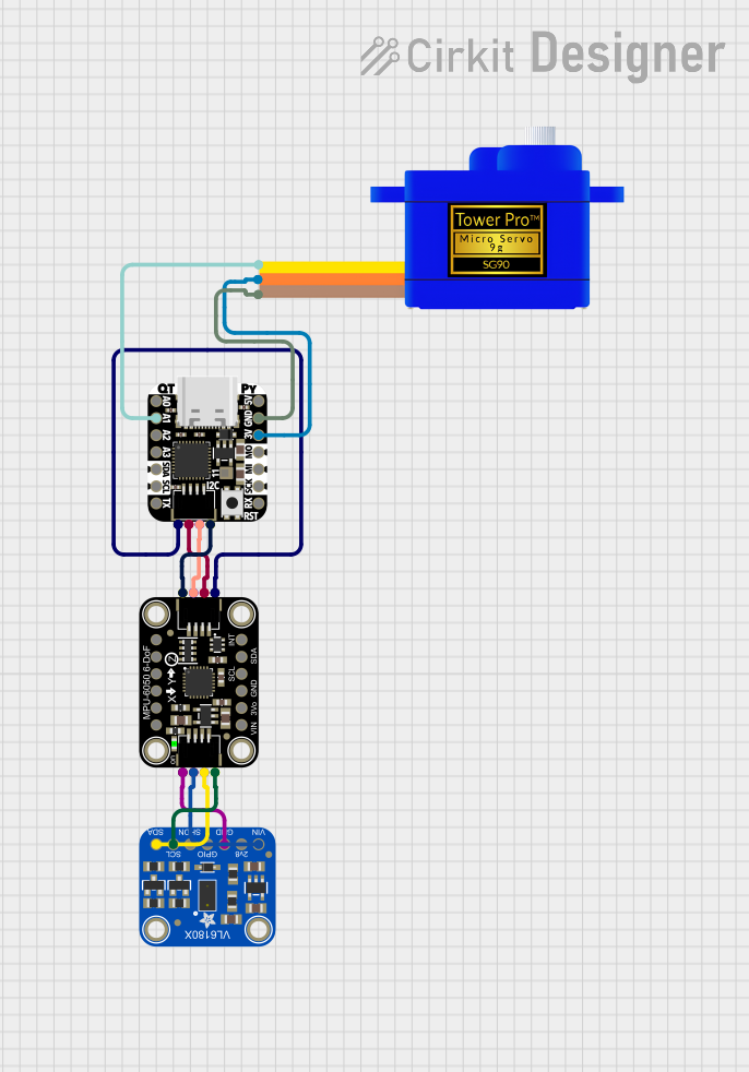
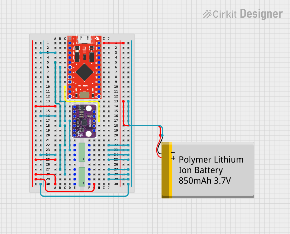
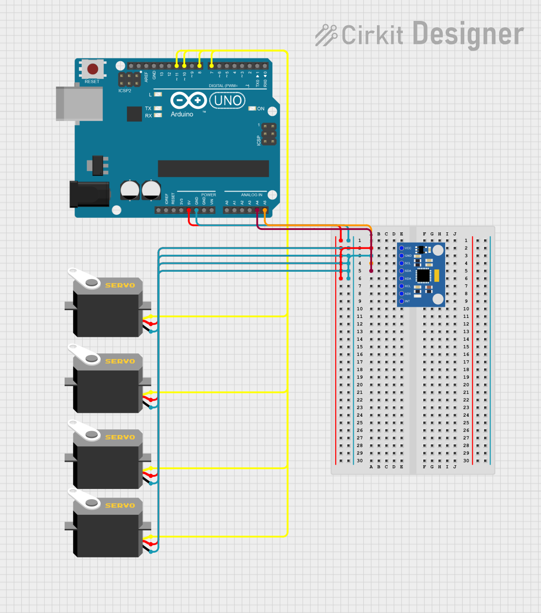
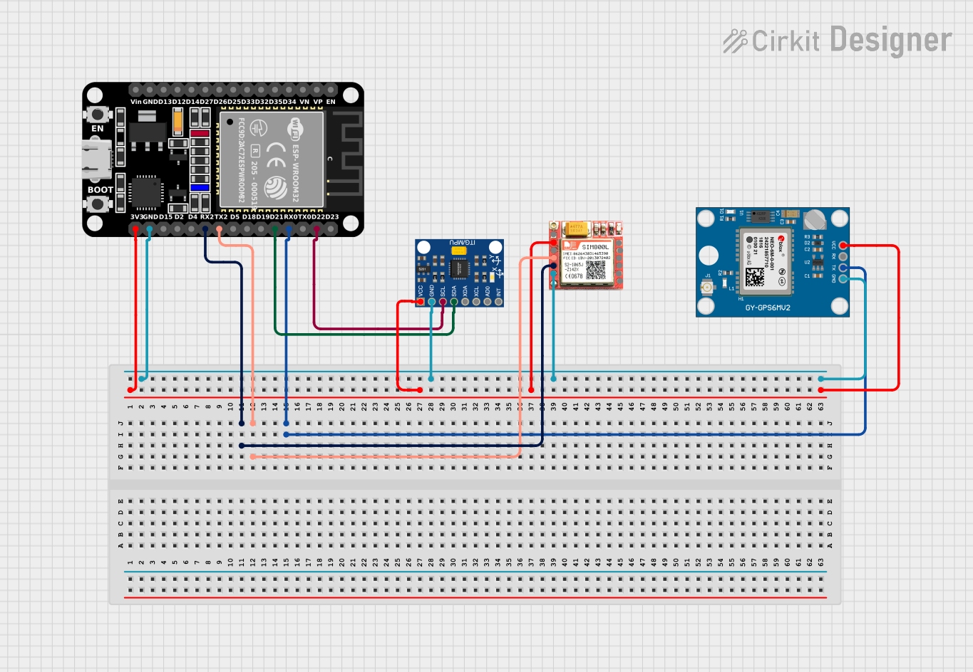
Explore Projects Built with ST-GYRO-PY
 Open Project in Cirkit Designer
 Open Project in Cirkit Designer
 Open Project in Cirkit Designer
 Open Project in Cirkit Designer
Explore Projects Built with ST-GYRO-PY
Open Project in Cirkit DesignerOpen Project in Cirkit DesignerOpen Project in Cirkit DesignerOpen Project in Cirkit DesignerCommon Applications:
- Robotics for motion control and stabilization
- Drones for orientation and navigation
- Gaming controllers for motion-based input
- Wearable devices for activity tracking
- Industrial equipment for vibration and motion analysis
Technical Specifications
Below are the key technical details of the ST-GYRO-PY module:
| Parameter | Value |
|---|---|
| Operating Voltage | 3.3V to 5V |
| Operating Current | 5 mA (typical) |
| Measurement Range | ±250, ±500, ±1000, ±2000 °/s |
| Communication Protocol | I2C and SPI |
| I2C Address | 0x68 (default) |
| Output Data Rate | Up to 8 kHz |
| Operating Temperature | -40°C to +85°C |
| Dimensions | 20mm x 15mm x 3mm |
Pin Configuration and Descriptions
The ST-GYRO-PY module has 8 pins, as described in the table below:
| Pin | Name | Description |
|---|---|---|
| 1 | VCC | Power supply input (3.3V to 5V) |
| 2 | GND | Ground connection |
| 3 | SCL | I2C clock line (used for I2C communication) |
| 4 | SDA | I2C data line (used for I2C communication) |
| 5 | CS | Chip Select (used for SPI communication; active low) |
| 6 | SDO | SPI data output (or I2C address selection: HIGH = 0x69, LOW = 0x68) |
| 7 | INT | Interrupt pin (used to signal data availability or events) |
| 8 | NC | Not connected (reserved for future use) |
Usage Instructions
Connecting the ST-GYRO-PY to an Arduino UNO
To use the ST-GYRO-PY module with an Arduino UNO, follow these steps:
Wiring:
- Connect the VCC pin to the Arduino's 5V pin.
- Connect the GND pin to the Arduino's GND pin.
- Connect the SCL pin to the Arduino's A5 pin (I2C clock line).
- Connect the SDA pin to the Arduino's A4 pin (I2C data line).
Install Required Libraries:
- Install the
Wirelibrary (pre-installed with Arduino IDE). - Optionally, install a gyroscope-specific library like
Adafruit_MPU6050if compatible.
- Install the
Arduino Code Example: Below is an example code snippet to read angular velocity data from the ST-GYRO-PY module:
#include <Wire.h>

const int gyroAddress = 0x68; // Default I2C address for ST-GYRO-PY

void setup() {
  Wire.begin(); // Initialize I2C communication
  Serial.begin(9600); // Start serial communication for debugging

  // Wake up the gyroscope (write 0 to the power management register)
  Wire.beginTransmission(gyroAddress);
  Wire.write(0x6B); // Power management register
  Wire.write(0x00); // Set to 0 to wake up the sensor
  Wire.endTransmission();
}

void loop() {
  Wire.beginTransmission(gyroAddress);
  Wire.write(0x43); // Starting register for X-axis angular velocity
  Wire.endTransmission(false);
  Wire.requestFrom(gyroAddress, 6, true); // Request 6 bytes (X, Y, Z)

  // Read angular velocity data
  int16_t gyroX = (Wire.read() << 8) | Wire.read(); // Combine high and low bytes
  int16_t gyroY = (Wire.read() << 8) | Wire.read();
  int16_t gyroZ = (Wire.read() << 8) | Wire.read();

  // Print the data to the Serial Monitor
  Serial.print("Gyro X: ");
  Serial.print(gyroX);
  Serial.print(" | Gyro Y: ");
  Serial.print(gyroY);
  Serial.print(" | Gyro Z: ");
  Serial.println(gyroZ);

  delay(500); // Delay for readability
}
Important Considerations:
- Ensure the module is securely connected to avoid communication errors.
- Use pull-up resistors (4.7kΩ recommended) on the SCL and SDA lines if not already included on the module.
- Avoid exposing the module to extreme temperatures or vibrations beyond its rated limits.
- Calibrate the gyroscope before use to ensure accurate readings.
Troubleshooting and FAQs
Common Issues and Solutions:
No Data Output:
- Verify the wiring connections, especially the SCL and SDA lines.
- Ensure the module is powered correctly (3.3V to 5V).
- Check the I2C address (default is 0x68, but it may change if the SDO pin is HIGH).
Inaccurate Readings:
- Perform a calibration routine to eliminate bias and drift.
- Ensure the module is mounted securely to avoid external vibrations.
Arduino Not Detecting the Module:
- Use the
I2C Scannersketch to confirm the module's I2C address. - Check for loose connections or damaged wires.
- Use the
Interrupt Pin Not Working:
- Ensure the interrupt functionality is enabled in the module's configuration registers.
- Verify the interrupt pin connection to the Arduino.
FAQs:
Q: Can the ST-GYRO-PY be used with a Raspberry Pi?
A: Yes, the module supports I2C and SPI communication, making it compatible with Raspberry Pi. Use the appropriate GPIO pins for I2C or SPI connections.
Q: How do I change the I2C address?
A: The I2C address can be changed by setting the SDO pin HIGH (0x69) or LOW (0x68).
Q: Does the module require external pull-up resistors?
A: Some versions of the ST-GYRO-PY module include built-in pull-up resistors. If not, you will need to add 4.7kΩ resistors to the SCL and SDA lines.
Q: What is the maximum angular velocity the module can measure?
A: The module can measure angular velocity up to ±2000 °/s, depending on the selected range.
By following this documentation, you can effectively integrate and troubleshoot the ST-GYRO-PY module in your projects.