How to Use 4047 IC: Examples, Pinouts, and Specs
Introduction
The 4047 IC, manufactured by IC, is a versatile integrated circuit designed to operate as an astable multivibrator, monostable multivibrator, or phase-locked loop. Its flexibility makes it a popular choice for a wide range of applications, including timer circuits, frequency generation, signal modulation, and waveform generation. The IC is particularly valued for its low power consumption and ease of use in both digital and analog circuits.
Explore Projects Built with 4047 IC


Explore Projects Built with 4047 IC
Common Applications
- Timer circuits
- Frequency generation
- Pulse-width modulation (PWM)
- Signal modulation and demodulation
- Square wave and pulse generation
- Phase-locked loop (PLL) systems
Technical Specifications
The 4047 IC is a CMOS-based device with the following key specifications:
| Parameter | Value |
|---|---|
| Supply Voltage (Vcc) | 3V to 15V |
| Operating Current | 10 µA (typical) at 5V |
| Output Voltage | 0V to Vcc |
| Output Current | ±3.2 mA (maximum) |
| Frequency Range (Astable) | Up to 1 MHz |
| Temperature Range | -40°C to +85°C |
| Package Type | DIP-14, SOIC-14 |
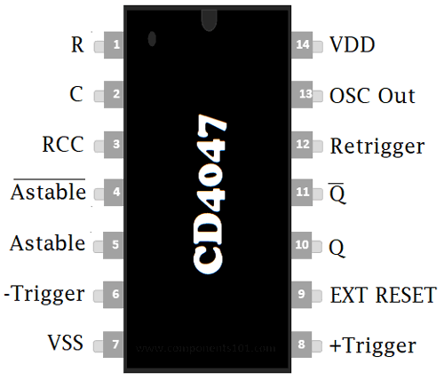
Pin Configuration and Descriptions
The 4047 IC comes in a 14-pin Dual Inline Package (DIP) or Small Outline Integrated Circuit (SOIC). Below is the pinout and description:
| Pin Number | Pin Name | Description |
|---|---|---|
| 1 | Astable Input A | Input for astable mode configuration. Connect to timing capacitor and resistor. |
| 2 | Astable Input B | Input for astable mode configuration. Connect to timing capacitor and resistor. |
| 3 | Astable/Monostable | Mode selection pin. High for astable mode, low for monostable mode. |
| 4 | Reset | Active low reset pin. Resets the IC when pulled low. |
| 5 | Trigger | Trigger input for monostable mode. |
| 6 | Q | Output pin for the generated waveform. |
| 7 | Q̅ (Q Bar) | Complementary output pin for the generated waveform. |
| 8 | GND | Ground pin. Connect to the negative terminal of the power supply. |
| 9 | Cext | External capacitor connection for timing. |
| 10 | Rext | External resistor connection for timing. |
| 11 | Vcc | Positive power supply pin. |
| 12 | NC | No connection. |
| 13 | NC | No connection. |
| 14 | Oscillator Out | Oscillator output for frequency monitoring. |
Usage Instructions
Using the 4047 IC in a Circuit
The 4047 IC can be configured in two primary modes: astable and monostable. Below are the steps to use the IC in each mode:
1. Astable Mode (Oscillator Mode)
- Connect a timing capacitor (Cext) between Pin 9 and GND.
- Connect a timing resistor (Rext) between Pin 10 and Vcc.
- Set Pin 3 (Astable/Monostable) to HIGH.
- The output frequency is determined by the values of Rext and Cext using the formula: [ f = \frac{1}{4.4 \times R_{ext} \times C_{ext}} ]
- The waveform will be available at Pin 6 (Q) and its complement at Pin 7 (Q̅).
2. Monostable Mode (One-Shot Mode)
- Connect a timing capacitor (Cext) between Pin 9 and GND.
- Connect a timing resistor (Rext) between Pin 10 and Vcc.
- Set Pin 3 (Astable/Monostable) to LOW.
- Apply a trigger pulse to Pin 5 (Trigger) to generate a single output pulse.
- The pulse width is determined by the values of Rext and Cext using the formula: [ T = 2.48 \times R_{ext} \times C_{ext} ]
Important Considerations
- Ensure that the supply voltage (Vcc) is within the specified range (3V to 15V).
- Use decoupling capacitors (e.g., 0.1 µF) near the Vcc and GND pins to reduce noise.
- Avoid exceeding the maximum output current of ±3.2 mA to prevent damage to the IC.
- For accurate timing, use precision resistors and capacitors with low tolerance values.
Example: Connecting the 4047 IC to an Arduino UNO
The 4047 IC can be used with an Arduino UNO to generate a square wave. Below is an example code to trigger the IC in monostable mode:
// Example: Triggering 4047 IC in Monostable Mode with Arduino UNO
const int triggerPin = 7; // Arduino pin connected to 4047 Trigger (Pin 5)
const int resetPin = 6;   // Arduino pin connected to 4047 Reset (Pin 4)

void setup() {
  pinMode(triggerPin, OUTPUT); // Set trigger pin as output
  pinMode(resetPin, OUTPUT);   // Set reset pin as output

  digitalWrite(resetPin, HIGH); // Ensure 4047 is not in reset state
}

void loop() {
  // Generate a trigger pulse
  digitalWrite(triggerPin, HIGH); // Set trigger pin HIGH
  delay(10);                      // Keep HIGH for 10 ms
  digitalWrite(triggerPin, LOW);  // Set trigger pin LOW

  delay(1000); // Wait for 1 second before the next pulse
}
Troubleshooting and FAQs
Common Issues and Solutions
No Output Signal
- Ensure that the supply voltage (Vcc) is connected and within the specified range.
- Verify that the timing components (Rext and Cext) are properly connected and functional.
- Check the mode selection pin (Pin 3) to ensure the correct mode is selected.
Incorrect Frequency or Pulse Width
- Double-check the values of Rext and Cext. Use components with low tolerance for better accuracy.
- Ensure that the formula for frequency or pulse width is correctly applied.
Output Signal is Noisy
- Add decoupling capacitors (e.g., 0.1 µF) near the Vcc and GND pins to reduce power supply noise.
- Use shielded cables or keep the circuit away from high-frequency noise sources.
IC Overheating
- Ensure that the output current does not exceed the maximum rating of ±3.2 mA.
- Verify that the supply voltage is within the specified range.
FAQs
Q1: Can the 4047 IC generate a sine wave?
A1: No, the 4047 IC is designed to generate square waves and pulses. For sine wave generation, additional circuitry such as filters is required.
Q2: What is the maximum frequency the 4047 IC can generate?
A2: The 4047 IC can generate frequencies up to 1 MHz in astable mode, depending on the values of Rext and Cext.
Q3: Can I use the 4047 IC with a 3.3V power supply?
A3: Yes, the 4047 IC operates with supply voltages as low as 3V, making it compatible with 3.3V systems.
Q4: What happens if I leave unused pins floating?
A4: It is recommended to connect unused input pins to a defined logic level (e.g., GND or Vcc) to avoid unpredictable behavior. Unused output pins can be left unconnected.