Cirkit Designer Logo
Cirkit Designer
Your all-in-one circuit design IDE
Home / 
Component Documentation

How to Use Adafruit TFT 2.8 inch 320x240 Touch w microSD: Examples, Pinouts, and Specs

Image of Adafruit TFT 2.8 inch 320x240 Touch w microSD
Cirkit Designer LogoDesign with Adafruit TFT 2.8 inch 320x240 Touch w microSD in Cirkit Designer

Introduction

The Adafruit TFT 2.8 inch 320x240 Touchscreen with microSD is a versatile and high-quality display module that features a 2.8-inch TFT LCD with a resolution of 320x240 pixels. This display is equipped with a resistive touch panel, allowing for user input and interaction, and a microSD card slot for additional storage capabilities. It is commonly used in embedded systems, DIY electronics projects, and interactive applications such as digital interfaces, gaming devices, and portable instruments.

Explore Projects Built with Adafruit TFT 2.8 inch 320x240 Touch w microSD

Use Cirkit Designer to design, explore, and prototype these projects online. Some projects support real-time simulation. Click "Open Project" to start designing instantly!
Arduino Mega 2560 Controlled TFT Touchscreen Interface
Image of Tablero Moto: A project utilizing Adafruit TFT 2.8 inch 320x240 Touch w microSD in a practical application
This circuit connects an Arduino Mega 2560 microcontroller to a 3.5-inch 480x320 TFT LCD display. The Arduino provides power, ground, and digital signals to control the display, including data lines for pixel information and control lines for reset, write, and command/data selection. The embedded code initializes the display and configures the Arduino's pins for communication, likely to create a user interface or visual output for a project.
Cirkit Designer LogoOpen Project in Cirkit Designer
ESP32-Based Data Display and RF Communication System
Image of Esp_Disp2: A project utilizing Adafruit TFT 2.8 inch 320x240 Touch w microSD in a practical application
This circuit features an ESP32 microcontroller connected to an ili9341 TFT display, an SD card module, and an E07-M1101D RF transceiver module. The ESP32 controls the display via GPIO pins and communicates with both the SD card and the RF module using SPI communication. The circuit is likely designed for applications requiring a user interface, data storage, and wireless communication capabilities.
Cirkit Designer LogoOpen Project in Cirkit Designer
ESP32 Wi-Fi Controlled Video Player with TFT Display and SD Card
Image of ESP32 : A project utilizing Adafruit TFT 2.8 inch 320x240 Touch w microSD in a practical application
This circuit features an ESP32 microcontroller interfaced with a TFT LCD display and a micro SD card module. The ESP32 is programmed to connect to a WiFi network, initialize the TFT display, and play video files from the SD card, providing a compact video playback system.
Cirkit Designer LogoOpen Project in Cirkit Designer
ESP32-Powered 1.3 inch TFT Display Module for Visual Data Output
Image of ESP32+ST7789: A project utilizing Adafruit TFT 2.8 inch 320x240 Touch w microSD in a practical application
This circuit connects an ESP32 microcontroller to a 1.3 inch TFT display module (ST7789). The ESP32 provides power and control signals to the display, enabling it to show graphical data.
Cirkit Designer LogoOpen Project in Cirkit Designer

Explore Projects Built with Adafruit TFT 2.8 inch 320x240 Touch w microSD

Use Cirkit Designer to design, explore, and prototype these projects online. Some projects support real-time simulation. Click "Open Project" to start designing instantly!
Image of Tablero Moto: A project utilizing Adafruit TFT 2.8 inch 320x240 Touch w microSD in a practical application
Arduino Mega 2560 Controlled TFT Touchscreen Interface
This circuit connects an Arduino Mega 2560 microcontroller to a 3.5-inch 480x320 TFT LCD display. The Arduino provides power, ground, and digital signals to control the display, including data lines for pixel information and control lines for reset, write, and command/data selection. The embedded code initializes the display and configures the Arduino's pins for communication, likely to create a user interface or visual output for a project.
Cirkit Designer LogoOpen Project in Cirkit Designer
Image of Esp_Disp2: A project utilizing Adafruit TFT 2.8 inch 320x240 Touch w microSD in a practical application
ESP32-Based Data Display and RF Communication System
This circuit features an ESP32 microcontroller connected to an ili9341 TFT display, an SD card module, and an E07-M1101D RF transceiver module. The ESP32 controls the display via GPIO pins and communicates with both the SD card and the RF module using SPI communication. The circuit is likely designed for applications requiring a user interface, data storage, and wireless communication capabilities.
Cirkit Designer LogoOpen Project in Cirkit Designer
Image of ESP32 : A project utilizing Adafruit TFT 2.8 inch 320x240 Touch w microSD in a practical application
ESP32 Wi-Fi Controlled Video Player with TFT Display and SD Card
This circuit features an ESP32 microcontroller interfaced with a TFT LCD display and a micro SD card module. The ESP32 is programmed to connect to a WiFi network, initialize the TFT display, and play video files from the SD card, providing a compact video playback system.
Cirkit Designer LogoOpen Project in Cirkit Designer
Image of ESP32+ST7789: A project utilizing Adafruit TFT 2.8 inch 320x240 Touch w microSD in a practical application
ESP32-Powered 1.3 inch TFT Display Module for Visual Data Output
This circuit connects an ESP32 microcontroller to a 1.3 inch TFT display module (ST7789). The ESP32 provides power and control signals to the display, enabling it to show graphical data.
Cirkit Designer LogoOpen Project in Cirkit Designer

Technical Specifications

General Features

  • Display Size: 2.8 inches diagonal
  • LCD Type: TFT
  • Resolution: 320x240 pixels
  • Interface: SPI
  • Touch Panel: Resistive
  • Onboard microSD card slot for storage
  • 4-wire resistive touch screen

Electrical Characteristics

  • Operating Voltage: 3.3V to 5V
  • Logic Level: 3.3V (5V tolerant)
  • Current Draw: 90mA (typical)

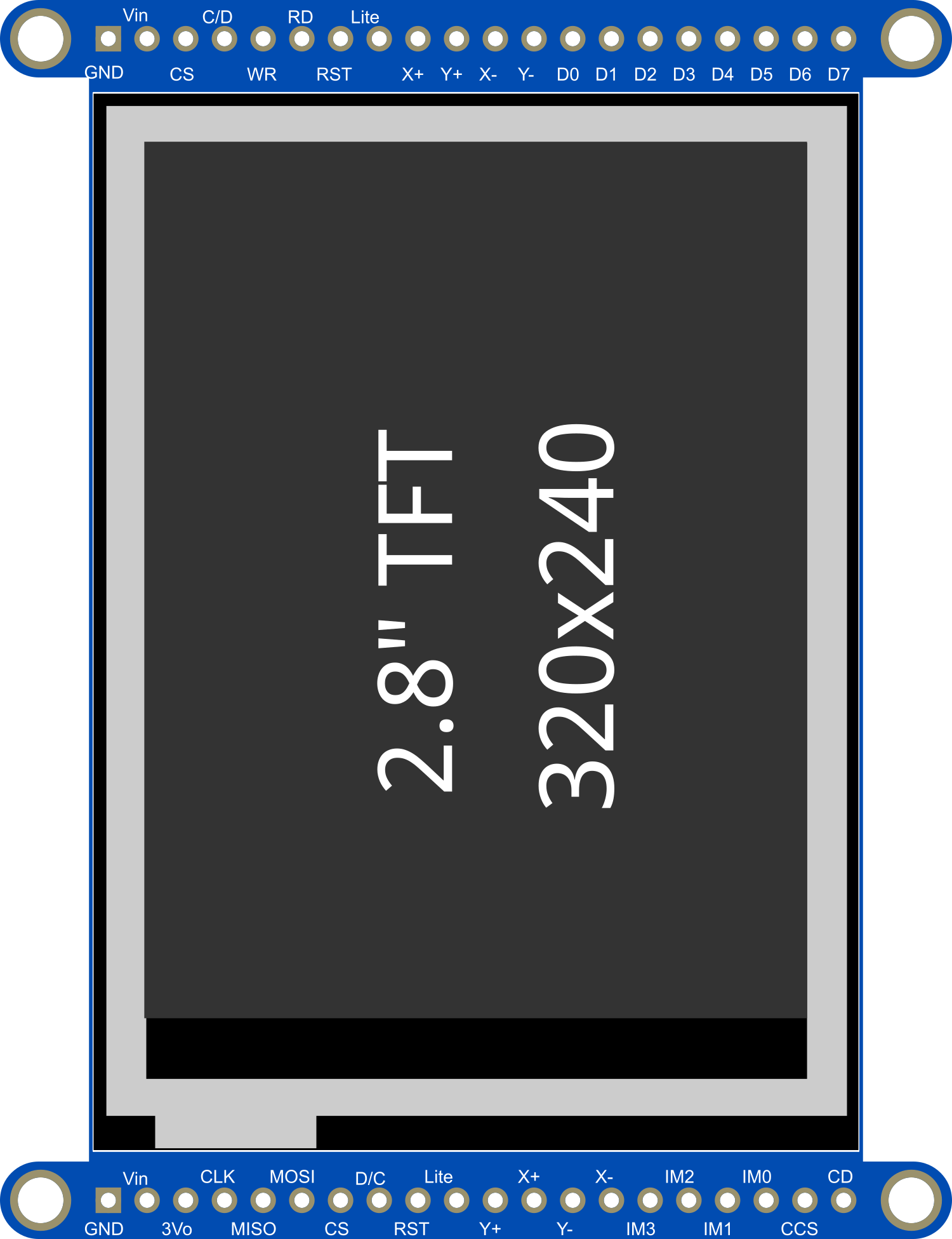
Pin Configuration and Descriptions

Pin Number Name Description
1 VCC Power supply (3.3V to 5V)
2 GND Ground
3 CS Chip Select for the TFT display
4 RESET Reset pin for the TFT
5 D/C Data/Command control pin
6 MOSI SPI Master Out Slave In
7 SCK SPI Clock
8 MISO SPI Master In Slave Out
9 T_CS Touchscreen Chip Select
10 SD_CS microSD Card Chip Select

Usage Instructions

Wiring the Display to an Arduino UNO

  1. Connect VCC to 5V on the Arduino.
  2. Connect GND to one of the GND pins on the Arduino.
  3. Connect CS to digital pin 10 on the Arduino.
  4. Connect RESET to digital pin 9 on the Arduino.
  5. Connect D/C to digital pin 8 on the Arduino.
  6. Connect MOSI to digital pin 11 on the Arduino.
  7. Connect SCK to digital pin 13 on the Arduino.
  8. Connect MISO to digital pin 12 on the Arduino.
  9. Connect T_CS to digital pin 4 on the Arduino.
  10. Connect SD_CS to digital pin 5 on the Arduino.

Initializing the Display

Before using the display, you need to install the Adafruit GFX and ST7735 libraries. You can install these through the Arduino Library Manager.

Sample Arduino Sketch

#include <Adafruit_GFX.h>    // Core graphics library
#include <Adafruit_ST7735.h> // Hardware-specific library
#include <SPI.h>

// Pin definitions
#define TFT_CS     10
#define TFT_RST    9
#define TFT_DC     8
#define TFT_MOSI   11  // Data out
#define TFT_SCLK   13  // Clock out

// Initialize Adafruit ST7735 TFT library
Adafruit_ST7735 tft = Adafruit_ST7735(TFT_CS, TFT_DC, TFT_MOSI, TFT_SCLK, TFT_RST);

void setup() {
  Serial.begin(9600);
  tft.initR(INITR_BLACKTAB);      // Initialize display
  tft.fillScreen(ST7735_BLACK);   // Clear the screen to black
}

void loop() {
  // Example: Draw a red filled rectangle
  tft.fillRect(10, 10, 50, 50, ST7735_RED);
  delay(500);

  // Example: Draw a green filled circle
  tft.fillCircle(90, 60, 30, ST7735_GREEN);
  delay(500);
}

Important Considerations and Best Practices

  • Always ensure that the power supply voltage and logic levels are compatible with the display.
  • Use a level shifter if you are interfacing with a 5V microcontroller.
  • Avoid applying pressure to the screen as it may damage the resistive touch panel.
  • When writing to the microSD card, ensure that the file operations are correctly handled to prevent data corruption.

Troubleshooting and FAQs

Common Issues

  • Display not powering on: Check the wiring, especially the VCC and GND connections. Ensure that the power supply is within the specified range.
  • Touch not responding: Verify that the T_CS pin is correctly connected and that the touch screen library is properly initialized in your code.
  • SD card not detected: Ensure that the SD_CS pin is correctly wired and that the microSD card is formatted correctly.

Solutions and Tips for Troubleshooting

  • Double-check all connections against the wiring diagram.
  • Use example sketches provided by the library to test basic functionality.
  • Check the Arduino Serial Monitor for any error messages or debug information.
  • Make sure that the libraries are up to date and correctly installed.

FAQs

Q: Can I use this display with other microcontrollers besides Arduino?

A: Yes, the display can be used with any microcontroller that supports SPI communication, provided that the logic levels are compatible.

Q: Is the touch panel multitouch?

A: No, the resistive touch panel is single-touch.

Q: How do I store images on the microSD card to display them on the screen?

A: Images can be stored on the microSD card in a compatible format (e.g., BMP). Libraries such as Adafruit_ImageReader can be used to load and display images from the card.

Q: Can I power the display with 3.3V?

A: Yes, the display can be powered with 3.3V, but ensure that the logic levels match the power supply to avoid damaging the display.