How to Use Buck Converter: Examples, Pinouts, and Specs
Introduction
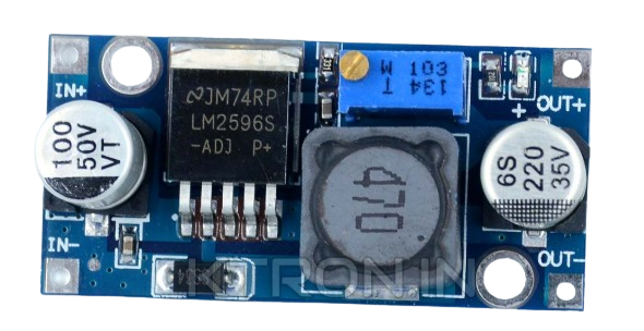
The Buck Converter (LM2596S), manufactured by Sharvi Technologies (OPC) Pvt. Ltd., is a DC-DC power converter designed to step down voltage efficiently while stepping up current. It achieves this through the use of a switching element, a diode, an inductor, and a capacitor. This component is widely used in applications requiring regulated lower voltage from a higher voltage source.
Explore Projects Built with Buck Converter


Explore Projects Built with Buck Converter
Common Applications and Use Cases
- Powering microcontrollers and embedded systems (e.g., Arduino, Raspberry Pi)
- Battery-powered devices to regulate voltage
- LED drivers and lighting systems
- Industrial automation and control systems
- Consumer electronics such as chargers and adapters
Technical Specifications
The following table outlines the key technical details of the LM2596S Buck Converter:
| Parameter | Value |
|---|---|
| Input Voltage Range | 4.5V to 40V |
| Output Voltage Range | 1.23V to 37V (adjustable) |
| Output Current | Up to 3A |
| Efficiency | Up to 92% |
| Switching Frequency | 150 kHz |
| Operating Temperature | -40°C to +125°C |
| Package Type | TO-220-5 |
Pin Configuration and Descriptions
The LM2596S Buck Converter has a 5-pin configuration as described below:
| Pin Number | Pin Name | Description |
|---|---|---|
| 1 | VIN | Input voltage pin. Connect to the unregulated DC input voltage. |
| 2 | Output | Regulated DC output voltage. Connect to the load. |
| 3 | Ground (GND) | Ground reference for the circuit. |
| 4 | Feedback | Voltage feedback pin. Used to set the output voltage via an external resistor. |
| 5 | ON/OFF | Enable/disable pin. Logic HIGH enables the converter; logic LOW disables it. |
Usage Instructions
How to Use the LM2596S in a Circuit
- Input Voltage Connection: Connect the input voltage (4.5V to 40V) to the VIN pin. Ensure the input voltage is higher than the desired output voltage.
- Output Voltage Adjustment: Use an external resistor divider network connected to the Feedback pin to set the desired output voltage. The formula for output voltage is: [ V_{OUT} = V_{REF} \times \left(1 + \frac{R1}{R2}\right) ] where ( V_{REF} = 1.23V ).
- Load Connection: Connect the load to the Output pin. Ensure the load does not exceed the maximum current rating of 3A.
- Enable/Disable Control: Use the ON/OFF pin to enable or disable the converter. Connect it to a logic HIGH (e.g., 5V) to enable or logic LOW (e.g., GND) to disable.
- Capacitor and Inductor Selection: Select appropriate values for the input capacitor, output capacitor, and inductor based on the desired output voltage and current. Refer to the datasheet for recommended values.
Important Considerations and Best Practices
- Use low Equivalent Series Resistance (ESR) capacitors for better performance.
- Place the input and output capacitors as close as possible to the VIN and Output pins to minimize noise.
- Ensure proper heat dissipation by using a heatsink if the converter operates at high currents.
- Avoid exceeding the maximum input voltage (40V) or output current (3A) to prevent damage.
Example: Connecting to an Arduino UNO
The LM2596S can be used to power an Arduino UNO by stepping down a 12V input to 5V. Below is an example Arduino sketch to demonstrate basic functionality:
// Example: Using LM2596S to power an Arduino UNO
// This sketch toggles an LED connected to pin 13

void setup() {
  pinMode(13, OUTPUT); // Set pin 13 as an output
}

void loop() {
  digitalWrite(13, HIGH); // Turn the LED on
  delay(1000);            // Wait for 1 second
  digitalWrite(13, LOW);  // Turn the LED off
  delay(1000);            // Wait for 1 second
}
Circuit Connection:
- Connect the LM2596S Output pin to the Arduino UNO's 5V pin.
- Connect the LM2596S Ground pin to the Arduino UNO's GND pin.
- Connect a 12V DC power source to the LM2596S VIN pin.
Troubleshooting and FAQs
Common Issues and Solutions
No Output Voltage:
- Verify that the input voltage is within the specified range (4.5V to 40V).
- Check the ON/OFF pin. Ensure it is connected to a logic HIGH to enable the converter.
- Inspect the circuit for loose connections or soldering issues.
Output Voltage is Incorrect:
- Double-check the resistor divider network connected to the Feedback pin.
- Ensure the input voltage is higher than the desired output voltage.
Overheating:
- Ensure the load current does not exceed 3A.
- Use a heatsink or improve ventilation around the component.
High Output Ripple:
- Use low ESR capacitors for the input and output.
- Place the capacitors as close as possible to the VIN and Output pins.
FAQs
Q1: Can the LM2596S be used with a battery as the input source?
A1: Yes, the LM2596S can be used with a battery as long as the input voltage is within the range of 4.5V to 40V.
Q2: What is the efficiency of the LM2596S?
A2: The efficiency can reach up to 92%, depending on the input voltage, output voltage, and load conditions.
Q3: Can I use the LM2596S to power a 3.3V device?
A3: Yes, you can adjust the output voltage to 3.3V using the resistor divider network.
Q4: Is the LM2596S suitable for audio applications?
A4: While the LM2596S is efficient, its switching frequency (150 kHz) may introduce noise in sensitive audio circuits. Additional filtering may be required.
By following this documentation, users can effectively integrate the LM2596S Buck Converter into their projects for efficient voltage regulation.