How to Use GLYPHSENSE-ICS43434: Examples, Pinouts, and Specs
Introduction
The GLYPHSENSE-ICS43434 is a high-performance MEMS (Micro-Electro-Mechanical Systems) microphone manufactured by PCBCUPID with the part ID GS-003. This microphone is designed for audio applications requiring low noise, high sensitivity, and excellent sound quality. It is ideal for use in voice recognition systems, sound capture devices, and other audio-related applications.
Explore Projects Built with GLYPHSENSE-ICS43434


Explore Projects Built with GLYPHSENSE-ICS43434
Common Applications and Use Cases
- Voice recognition systems (e.g., smart assistants)
- Audio recording devices
- IoT devices with sound detection capabilities
- Wearable electronics
- Smart home devices (e.g., smart speakers, security systems)
Technical Specifications
The following table outlines the key technical specifications of the GLYPHSENSE-ICS43434:
| Parameter | Value |
|---|---|
| Operating Voltage | 1.6V to 3.6V |
| Sensitivity | -26 dBFS ± 1 dB |
| Signal-to-Noise Ratio | 65 dB (typical) |
| Acoustic Overload Point | 120 dB SPL |
| Frequency Response | 50 Hz to 20 kHz |
| Current Consumption | 170 µA (typical) |
| Output Format | Pulse Density Modulation (PDM) |
| Operating Temperature | -40°C to +85°C |
| Package Dimensions | 3.5 mm x 2.65 mm x 0.98 mm |
Pin Configuration and Descriptions
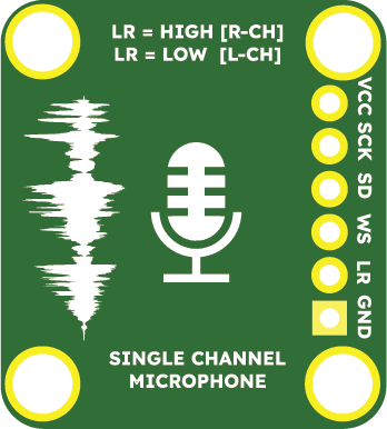
The GLYPHSENSE-ICS43434 has a 5-pin configuration. The table below describes each pin:
| Pin Name | Pin Number | Description |
|---|---|---|
| VDD | 1 | Power supply input (1.6V to 3.6V). |
| GND | 2 | Ground connection. |
| DATA | 3 | PDM data output. |
| CLK | 4 | Clock input for PDM interface. |
| SEL | 5 | Channel select (left or right audio channel). |
Usage Instructions
How to Use the Component in a Circuit
- Power Supply: Connect the VDD pin to a stable power source (1.6V to 3.6V) and the GND pin to the ground.
- Clock Signal: Provide a clock signal (typically 1 MHz to 3.25 MHz) to the CLK pin. This clock drives the PDM output.
- Data Output: Connect the DATA pin to a microcontroller or digital signal processor (DSP) capable of decoding PDM signals.
- Channel Selection: Use the SEL pin to configure the microphone as a left or right channel:
- Connect SEL to GND for the left channel.
- Connect SEL to VDD for the right channel.
Important Considerations and Best Practices
- Decoupling Capacitor: Place a 0.1 µF decoupling capacitor close to the VDD pin to reduce noise and ensure stable operation.
- Clock Signal Quality: Ensure the clock signal is clean and within the specified frequency range to avoid data corruption.
- PCB Layout: Minimize the trace length for the DATA and CLK lines to reduce signal degradation.
- Acoustic Design: Avoid obstructing the microphone's acoustic port to maintain optimal sound capture.
Example: Connecting to an Arduino UNO
The GLYPHSENSE-ICS43434 can be interfaced with an Arduino UNO for basic audio capture. Below is an example circuit and code:
Circuit Connections
| GLYPHSENSE-ICS43434 Pin | Arduino UNO Pin |
|---|---|
| VDD | 3.3V |
| GND | GND |
| DATA | Digital Pin 2 |
| CLK | Digital Pin 3 |
| SEL | GND (Left Channel) |
Arduino Code
// Example code for interfacing GLYPHSENSE-ICS43434 with Arduino UNO
// This code captures PDM data and processes it for basic audio analysis.

#include <PDM.h> // Include the PDM library for handling PDM microphones

// Define the PDM microphone pins
#define PDM_DATA_PIN 2
#define PDM_CLK_PIN 3

// Buffer to store audio samples
#define BUFFER_SIZE 256
int16_t audioBuffer[BUFFER_SIZE];

// Callback function to handle incoming PDM data
void onPDMData() {
  // Read PDM data into the buffer
  int bytesAvailable = PDM.available();
  PDM.read(audioBuffer, bytesAvailable);
}

void setup() {
  // Initialize serial communication for debugging
  Serial.begin(9600);
  while (!Serial);

  // Configure the PDM microphone
  if (!PDM.begin(1, 16000)) { // Mono channel, 16 kHz sample rate
    Serial.println("Failed to initialize PDM microphone!");
    while (1);
  }

  // Set the PDM data callback
  PDM.onReceive(onPDMData);

  Serial.println("PDM microphone initialized successfully.");
}

void loop() {
  // Process audio data (e.g., print the first sample for debugging)
  if (PDM.available()) {
    Serial.println(audioBuffer[0]); // Print the first sample
  }
}
Notes:
- The
PDMlibrary is required for this example. Install it via the Arduino Library Manager. - The code assumes a 16 kHz sample rate and mono audio. Adjust settings as needed for your application.
Troubleshooting and FAQs
Common Issues and Solutions
No Output from the Microphone
- Ensure the VDD and GND pins are properly connected.
- Verify that the clock signal is within the specified frequency range (1 MHz to 3.25 MHz).
- Check the SEL pin configuration for the correct audio channel.
Noisy or Distorted Audio
- Use a clean power supply and add a decoupling capacitor near the VDD pin.
- Ensure the clock signal is stable and free of jitter.
- Avoid placing the microphone near high-frequency noise sources.
Microphone Not Detected by the Microcontroller
- Verify the connections between the DATA and CLK pins and the microcontroller.
- Check the microcontroller's PDM decoding configuration.
FAQs
Q: Can the GLYPHSENSE-ICS43434 be used in stereo applications?
A: Yes, by using two microphones and configuring the SEL pin on each for left and right channels, you can achieve stereo audio capture.
Q: What is the maximum sound pressure level the microphone can handle?
A: The GLYPHSENSE-ICS43434 can handle up to 120 dB SPL without distortion.
Q: Is the microphone suitable for outdoor use?
A: The microphone operates in a wide temperature range (-40°C to +85°C), but additional protection may be required for exposure to moisture or dust.
Q: Can I use this microphone with a 5V power supply?
A: No, the maximum operating voltage is 3.6V. Use a voltage regulator to step down 5V to a suitable level.
This concludes the documentation for the GLYPHSENSE-ICS43434. For further assistance, refer to the manufacturer's datasheet or contact PCBCUPID support.