How to Use Gc9a01 display: Examples, Pinouts, and Specs
Introduction
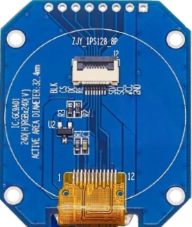
The GC9A01 display is a compact, high-resolution TFT LCD screen designed for use in embedded systems and microcontroller projects. It features a circular form factor, vibrant colors, and a wide viewing angle, making it ideal for applications requiring visually appealing graphical interfaces. The display supports SPI communication, which ensures fast and efficient data transfer, even in resource-constrained environments.
Explore Projects Built with Gc9a01 display

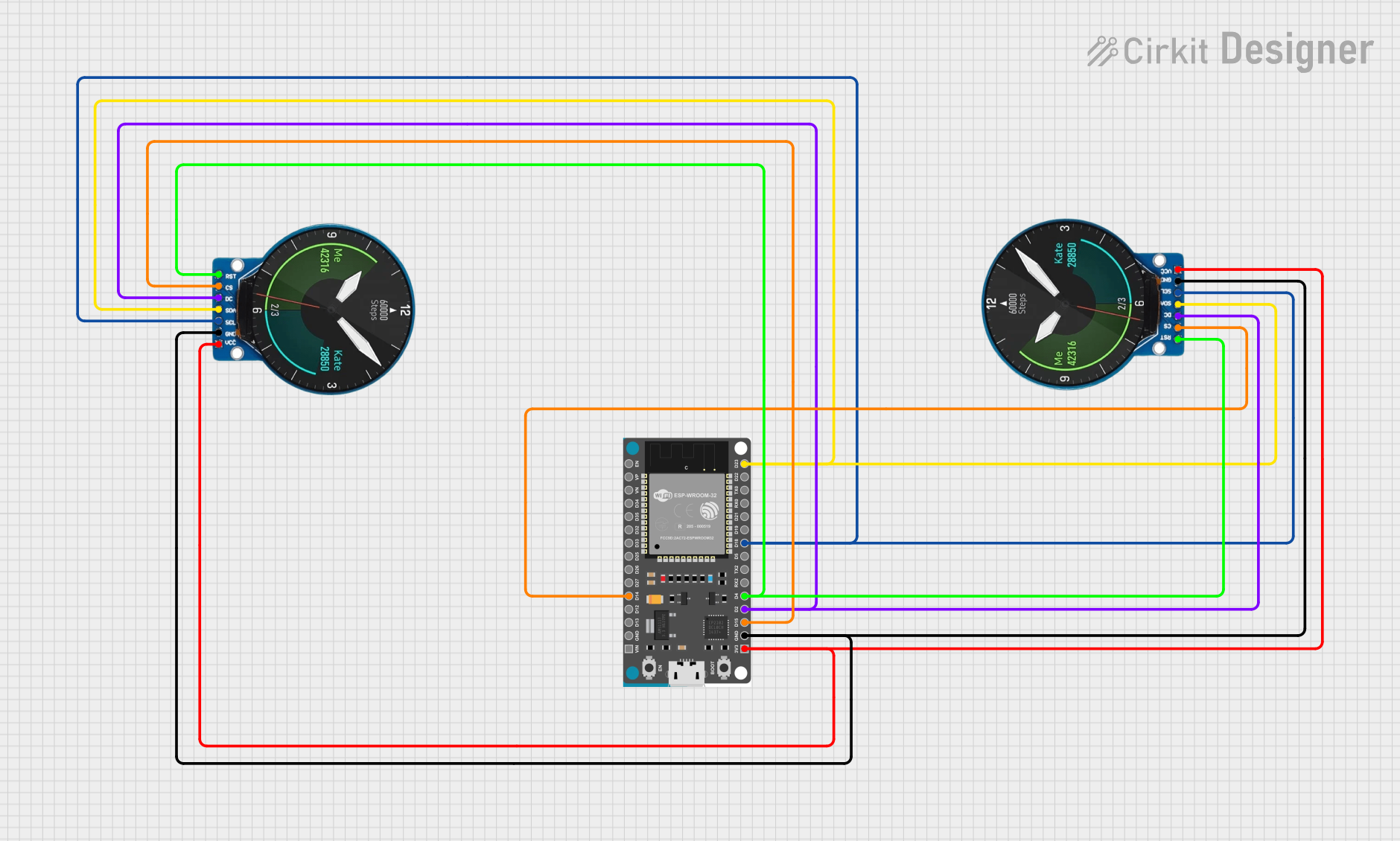
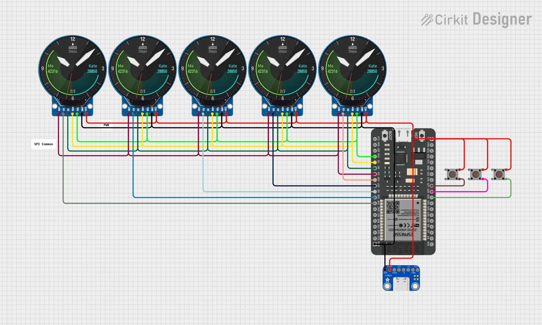
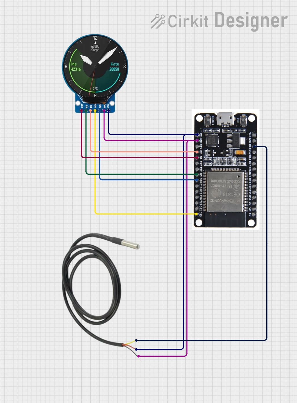
Explore Projects Built with Gc9a01 display
Common Applications and Use Cases
- Smartwatches and wearable devices
- IoT dashboards and control panels
- Portable gaming consoles
- Industrial equipment displays
- Educational and hobbyist projects
Technical Specifications
The GC9A01 display is a versatile component with the following key specifications:
| Parameter | Value |
|---|---|
| Display Type | TFT LCD |
| Resolution | 240 x 240 pixels |
| Display Size | 1.28 inches (circular) |
| Interface | SPI (Serial Peripheral Interface) |
| Operating Voltage | 3.3V |
| Backlight Voltage | 3.0V to 3.3V |
| Current Consumption | ~20mA (typical) |
| Viewing Angle | Wide (up to 160°) |
| Color Depth | 65K (16-bit RGB) |
| Driver IC | GC9A01 |
Pin Configuration and Descriptions
The GC9A01 display typically has the following pinout:
| Pin Name | Description |
|---|---|
| VCC | Power supply input (3.3V) |
| GND | Ground |
| SCL | SPI clock signal |
| SDA | SPI data signal (MOSI) |
| RES | Reset pin (active low) |
| DC | Data/Command control pin |
| CS | Chip select (active low) |
| BLK | Backlight control (PWM or constant high for always on) |
Usage Instructions
How to Use the GC9A01 Display in a Circuit
- Power Supply: Connect the
VCCpin to a 3.3V power source and theGNDpin to ground. - SPI Communication: Connect the
SCL(SPI clock) andSDA(SPI data) pins to the corresponding SPI pins on your microcontroller. - Control Pins:
- Connect the
RESpin to a GPIO pin on your microcontroller for resetting the display. - Use the
DCpin to toggle between data and command modes. - Connect the
CSpin to a GPIO pin to enable or disable the display.
- Connect the
- Backlight: Connect the
BLKpin to a PWM-capable GPIO pin for brightness control, or tie it to 3.3V for constant backlight.
Important Considerations and Best Practices
- Voltage Levels: Ensure all signal lines operate at 3.3V logic levels. Use a level shifter if your microcontroller operates at 5V.
- SPI Speed: Use an SPI clock speed of up to 10 MHz for optimal performance.
- Initialization: The display requires specific initialization commands to function correctly. Use a compatible library or refer to the GC9A01 datasheet for details.
- Backlight Control: To extend the display's lifespan, avoid running the backlight at maximum brightness for prolonged periods.
Example Code for Arduino UNO
Below is an example of how to use the GC9A01 display with an Arduino UNO. This example uses the popular Adafruit_GFX and Adafruit_GC9A01 libraries.
#include <Adafruit_GFX.h>       // Core graphics library
#include <Adafruit_GC9A01.h>    // GC9A01 driver library
#include <SPI.h>                // SPI library

// Define pin connections
#define TFT_CS   10  // Chip select pin
#define TFT_DC    9  // Data/Command pin
#define TFT_RST   8  // Reset pin

// Create display object
Adafruit_GC9A01 tft = Adafruit_GC9A01(TFT_CS, TFT_DC, TFT_RST);

void setup() {
  // Initialize serial communication for debugging
  Serial.begin(9600);
  Serial.println("GC9A01 Display Test");

  // Initialize the display
  tft.begin();
  tft.setRotation(0);  // Set display orientation
  tft.fillScreen(0x0000);  // Clear screen (black)

  // Display a test message
  tft.setTextColor(0xFFFF);  // Set text color (white)
  tft.setTextSize(2);        // Set text size
  tft.setCursor(20, 50);     // Set cursor position
  tft.println("Hello, GC9A01!");
}

void loop() {
  // Add your code here to update the display
}
Notes:
- Install the
Adafruit_GFXandAdafruit_GC9A01libraries via the Arduino Library Manager before running the code. - Ensure the SPI pins on the Arduino UNO (MOSI: pin 11, SCK: pin 13) are connected to the
SDAandSCLpins of the display, respectively.
Troubleshooting and FAQs
Common Issues and Solutions
No Display Output:
- Verify all connections, especially power (VCC and GND) and SPI lines.
- Ensure the
CS,DC, andRESpins are correctly connected and configured in the code. - Check if the display initialization commands are being sent correctly.
Flickering or Distorted Graphics:
- Reduce the SPI clock speed to improve signal integrity.
- Ensure proper grounding and minimize noise in the circuit.
Backlight Not Turning On:
- Confirm the
BLKpin is connected to 3.3V or a PWM signal. - Check the backlight voltage (should be between 3.0V and 3.3V).
- Confirm the
Partial or Incorrect Display:
- Verify the display resolution (240x240) is correctly set in the code.
- Ensure the
Adafruit_GC9A01library is up to date.
FAQs
Q: Can I use the GC9A01 display with a 5V microcontroller?
A: Yes, but you must use level shifters to convert the 5V logic signals to 3.3V to avoid damaging the display.
Q: What is the maximum SPI clock speed supported by the GC9A01?
A: The GC9A01 supports SPI clock speeds of up to 10 MHz. However, lower speeds may be required for longer cables or noisy environments.
Q: Can I control the backlight brightness?
A: Yes, connect the BLK pin to a PWM-capable GPIO pin on your microcontroller to adjust brightness.
Q: Is the GC9A01 display compatible with other microcontrollers?
A: Yes, the display is compatible with most microcontrollers that support SPI communication, including ESP32, STM32, and Raspberry Pi.
By following this documentation, you can effectively integrate the GC9A01 display into your projects and troubleshoot common issues.