How to Use esp8266 nodemcu : Examples, Pinouts, and Specs
Introduction
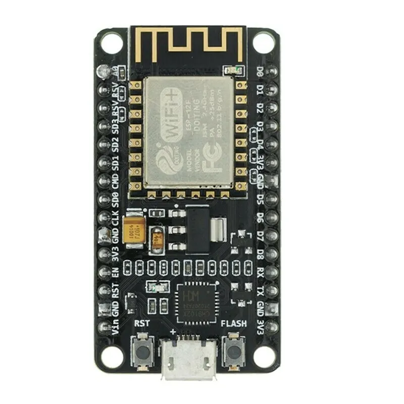
The ESP8266 NodeMCU, manufactured by Lolin, is a low-cost Wi-Fi microcontroller module with an integrated TCP/IP protocol stack. It is widely used for Internet of Things (IoT) applications due to its versatility and ease of use. The module features General Purpose Input/Output (GPIO), Pulse Width Modulation (PWM), Inter-Integrated Circuit (I2C), 1-Wire, and Analog-to-Digital Converter (ADC) capabilities, making it suitable for a wide range of projects.
Explore Projects Built with esp8266 nodemcu
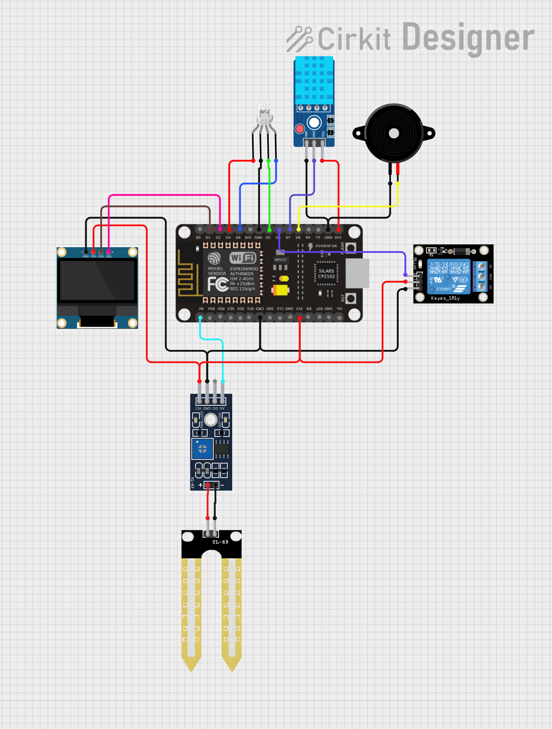

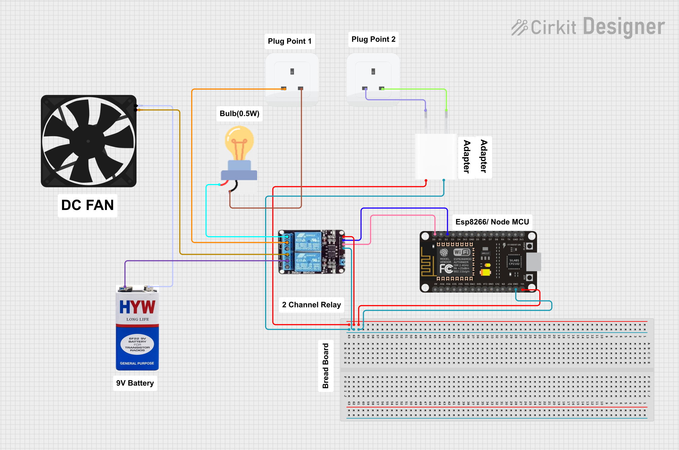
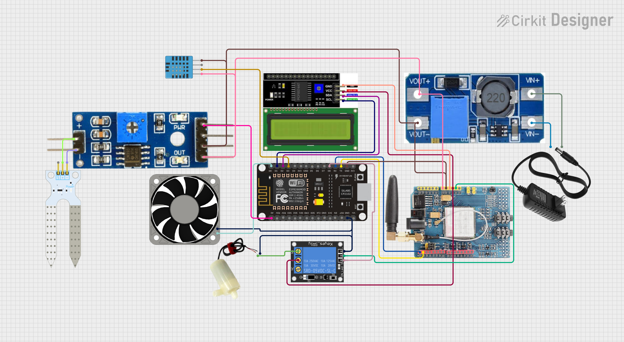
Explore Projects Built with esp8266 nodemcu
Common Applications and Use Cases
- Home Automation: Control lights, appliances, and other devices remotely.
- IoT Projects: Collect and transmit sensor data to the cloud.
- Wireless Data Logging: Store data wirelessly on a server or cloud service.
- Prototyping: Rapid development of connected devices and systems.
- Educational Projects: Learn about microcontrollers, networking, and IoT.
Technical Specifications
Key Technical Details
| Parameter | Value |
|---|---|
| Microcontroller | ESP8266 |
| Operating Voltage | 3.3V |
| Input Voltage | 7-12V |
| Digital I/O Pins | 11 |
| Analog Input Pins | 1 (10-bit ADC) |
| Flash Memory | 4MB (32Mb) |
| SRAM | 64KB |
| Clock Speed | 80MHz (can be overclocked to 160MHz) |
| Wi-Fi Standards | 802.11 b/g/n |
| Wi-Fi Security | WPA/WPA2 |
| Interfaces | UART, SPI, I2C, PWM, GPIO, ADC |
| Dimensions | 58mm x 31mm x 13mm |
Pin Configuration and Descriptions
| Pin | Name | Function |
|---|---|---|
| 1 | GND | Ground |
| 2 | 3V3 | 3.3V Power Supply |
| 3 | EN | Chip Enable (Active High) |
| 4 | RST | Reset (Active Low) |
| 5 | VIN | External Power Supply (7-12V) |
| 6 | D0 | GPIO16 |
| 7 | D1 | GPIO5 (SCL) |
| 8 | D2 | GPIO4 (SDA) |
| 9 | D3 | GPIO0 |
| 10 | D4 | GPIO2 (TXD1) |
| 11 | D5 | GPIO14 (HSCLK) |
| 12 | D6 | GPIO12 (HMISO) |
| 13 | D7 | GPIO13 (HMOSI) |
| 14 | D8 | GPIO15 (HCS) |
| 15 | RX | GPIO3 (RXD0) |
| 16 | TX | GPIO1 (TXD0) |
| 17 | A0 | Analog Input (0-1V) |
Usage Instructions
How to Use the Component in a Circuit
Power Supply:
- Connect the
VINpin to a 7-12V power source or use the3V3pin for a 3.3V regulated supply. - Connect the
GNDpin to the ground of your circuit.
- Connect the
Connecting to an Arduino UNO:
- Connect the
TXpin of the ESP8266 to theRXpin of the Arduino. - Connect the
RXpin of the ESP8266 to theTXpin of the Arduino. - Ensure the
GNDpins of both devices are connected.
- Connect the
Programming:
- Use the Arduino IDE to program the ESP8266. Select the appropriate board (
NodeMCU 1.0 (ESP-12E Module)) from the Tools menu.
- Use the Arduino IDE to program the ESP8266. Select the appropriate board (
Important Considerations and Best Practices
- Voltage Levels: Ensure that the ESP8266 operates at 3.3V. Using higher voltages can damage the module.
- Power Supply: Provide a stable power supply to avoid unexpected resets or malfunctions.
- GPIO Usage: Be mindful of the GPIO pin states during boot. Some pins have specific functions during the boot process.
- Antenna Placement: For optimal Wi-Fi performance, ensure the antenna area is free from obstructions and metallic objects.
Example Code
Here is an example code to connect the ESP8266 NodeMCU to a Wi-Fi network and print the IP address:
#include <ESP8266WiFi.h>

// Replace with your network credentials
const char* ssid = "your_SSID";
const char* password = "your_PASSWORD";

void setup() {
  Serial.begin(115200); // Initialize serial communication
  delay(10);

  // Connect to Wi-Fi network
  Serial.println();
  Serial.print("Connecting to ");
  Serial.println(ssid);

  WiFi.begin(ssid, password);

  while (WiFi.status() != WL_CONNECTED) {
    delay(500);
    Serial.print(".");
  }

  Serial.println("");
  Serial.println("WiFi connected");
  Serial.println("IP address: ");
  Serial.println(WiFi.localIP()); // Print the IP address
}

void loop() {
  // Put your main code here, to run repeatedly
}
Troubleshooting and FAQs
Common Issues Users Might Face
ESP8266 Not Connecting to Wi-Fi:
- Solution: Double-check the SSID and password. Ensure the Wi-Fi network is within range and not overloaded.
Module Not Responding:
- Solution: Verify the power supply. Ensure the
ENpin is connected to3V3and theRSTpin is not grounded.
- Solution: Verify the power supply. Ensure the
Serial Communication Issues:
- Solution: Ensure the correct baud rate is set in the serial monitor. Check the connections between the ESP8266 and the Arduino.
Solutions and Tips for Troubleshooting
- Power Supply: Use a dedicated power supply for the ESP8266 to avoid power-related issues.
- Firmware Update: Ensure the ESP8266 firmware is up to date for optimal performance and compatibility.
- Debugging: Use the serial monitor to print debug information and identify issues.
By following this documentation, users can effectively utilize the ESP8266 NodeMCU in their projects, whether they are beginners or experienced developers.