Cirkit Designer Logo
Cirkit Designer
Your all-in-one circuit design IDE
Home / 
Component Documentation

How to Use 3.3V regulator: Examples, Pinouts, and Specs

Image of 3.3V regulator
Cirkit Designer LogoDesign with 3.3V regulator in Cirkit Designer

Introduction

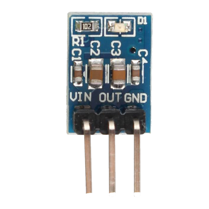
The AMS1117 3.3 is a low dropout voltage regulator that provides a regulated output of 3.3V. It is designed by Advanced Monolithic Systems to deliver up to 1A of output current. The device is ideal for powering 3.3V logic levels in digital circuits, microcontrollers, and other sensitive electronic devices that require a stable power supply.

Explore Projects Built with 3.3V regulator

Use Cirkit Designer to design, explore, and prototype these projects online. Some projects support real-time simulation. Click "Open Project" to start designing instantly!
Battery-Powered 18650 Li-ion Charger with USB Output and Adjustable Voltage Regulator
Image of Breadboard: A project utilizing 3.3V regulator in a practical application
This circuit is a battery management and power supply system that uses three 3.7V batteries connected to a 3S 10A Li-ion 18650 Charger Protection Board Module for balanced charging and protection. The system includes a TP4056 Battery Charging Protection Module for additional charging safety, a Step Up Boost Power Converter to regulate and boost the voltage, and a USB regulator to provide a stable 5V output, controlled by a push switch.
Cirkit Designer LogoOpen Project in Cirkit Designer
ESP32-Powered Wi-Fi Enabled Microcontroller Circuit with AMS1117 Voltage Regulation
Image of Power regualator: A project utilizing 3.3V regulator in a practical application
This circuit features an ESP32 microcontroller powered by a 3.3V AMS1117 voltage regulator. The power is supplied through a 2.1mm DC barrel jack, which provides the input voltage to the AMS1117, and the regulated 3.3V output is connected to the ESP32's VIN pin. The ground connections are shared among the ESP32 and the voltage regulator.
Cirkit Designer LogoOpen Project in Cirkit Designer
Battery-Powered LED Control Circuit with Potentiometer and Transistors
Image of STROBE LIGHTS: A project utilizing 3.3V regulator in a practical application
This circuit is a regulated power supply with a 12V battery input, a 7805 voltage regulator providing a 5V output, and a potentiometer for adjustable voltage control. It includes transistors and resistors for current regulation and an LED indicator to show the operational status.
Cirkit Designer LogoOpen Project in Cirkit Designer
Adjustable LM317 Voltage Regulator with ESP32 Control
Image of Reciever: A project utilizing 3.3V regulator in a practical application
This circuit is a variable voltage power supply featuring an LM317 voltage regulator for adjustable output. It includes an ESP32 microcontroller powered through the regulator, with input and output voltage stabilization provided by tantalum capacitors. A rotary potentiometer is used to set the desired voltage level.
Cirkit Designer LogoOpen Project in Cirkit Designer

Explore Projects Built with 3.3V regulator

Use Cirkit Designer to design, explore, and prototype these projects online. Some projects support real-time simulation. Click "Open Project" to start designing instantly!
Image of Breadboard: A project utilizing 3.3V regulator in a practical application
Battery-Powered 18650 Li-ion Charger with USB Output and Adjustable Voltage Regulator
This circuit is a battery management and power supply system that uses three 3.7V batteries connected to a 3S 10A Li-ion 18650 Charger Protection Board Module for balanced charging and protection. The system includes a TP4056 Battery Charging Protection Module for additional charging safety, a Step Up Boost Power Converter to regulate and boost the voltage, and a USB regulator to provide a stable 5V output, controlled by a push switch.
Cirkit Designer LogoOpen Project in Cirkit Designer
Image of Power regualator: A project utilizing 3.3V regulator in a practical application
ESP32-Powered Wi-Fi Enabled Microcontroller Circuit with AMS1117 Voltage Regulation
This circuit features an ESP32 microcontroller powered by a 3.3V AMS1117 voltage regulator. The power is supplied through a 2.1mm DC barrel jack, which provides the input voltage to the AMS1117, and the regulated 3.3V output is connected to the ESP32's VIN pin. The ground connections are shared among the ESP32 and the voltage regulator.
Cirkit Designer LogoOpen Project in Cirkit Designer
Image of STROBE LIGHTS: A project utilizing 3.3V regulator in a practical application
Battery-Powered LED Control Circuit with Potentiometer and Transistors
This circuit is a regulated power supply with a 12V battery input, a 7805 voltage regulator providing a 5V output, and a potentiometer for adjustable voltage control. It includes transistors and resistors for current regulation and an LED indicator to show the operational status.
Cirkit Designer LogoOpen Project in Cirkit Designer
Image of Reciever: A project utilizing 3.3V regulator in a practical application
Adjustable LM317 Voltage Regulator with ESP32 Control
This circuit is a variable voltage power supply featuring an LM317 voltage regulator for adjustable output. It includes an ESP32 microcontroller powered through the regulator, with input and output voltage stabilization provided by tantalum capacitors. A rotary potentiometer is used to set the desired voltage level.
Cirkit Designer LogoOpen Project in Cirkit Designer

Common Applications and Use Cases

  • Power supply for 3.3V logic circuits
  • Microcontroller power source
  • Battery-powered devices
  • Peripheral power supply for computers and communication equipment

Technical Specifications

Key Technical Details

  • Output Voltage: 3.3V
  • Output Current: Up to 1A
  • Dropout Voltage: Typically 1.1V at 800mA load
  • Input Voltage Range: 4.75V to 15V
  • Quiescent Current: 5mA (typical)
  • Package: SOT-223, TO-252 (DPAK)

Pin Configuration and Descriptions

Pin Number Name Description
1 GND Ground reference for the regulator
2 VOUT Regulated 3.3V output
3 VIN Input voltage (4.75V to 15V)

Usage Instructions

How to Use the Component in a Circuit

  1. Connect the VIN pin to your input voltage source, which should be in the range of 4.75V to 15V.
  2. Connect the GND pin to the common ground of your circuit.
  3. The VOUT pin will provide a stable 3.3V output. Connect this to the power input of your 3.3V devices.

Important Considerations and Best Practices

  • Always ensure that the input voltage does not exceed the maximum rating of 15V.
  • A capacitor (typically 10µF) should be placed close to the input and output pins to stabilize the voltage and reduce noise.
  • Avoid loading the regulator with a current higher than 1A to prevent overheating and potential damage.
  • Provide adequate heat sinking if the regulator is expected to dissipate significant power due to high load or input voltage.

Troubleshooting and FAQs

Common Issues

  • Voltage Drop: If the input voltage is too close to 3.3V, the regulator may not be able to maintain a stable output due to insufficient dropout voltage.
  • Overheating: Excessive power dissipation can cause the regulator to overheat, especially if the input voltage is high and the load is near 1A.

Solutions and Tips for Troubleshooting

  • Ensure that the input voltage is at least 1.1V higher than the desired output voltage.
  • Check for proper heat sinking and airflow around the regulator.
  • Verify that the capacitors are correctly placed and are of the recommended value.

FAQs

Q: Can I use the AMS1117 3.3 to power a 3.3V microcontroller? A: Yes, the AMS1117 3.3 is suitable for powering 3.3V microcontrollers as long as the current requirements do not exceed 1A.

Q: What is the maximum input voltage for the AMS1117 3.3? A: The maximum input voltage is 15V. Exceeding this voltage can damage the regulator.

Q: Do I need external capacitors for stability? A: Yes, it is recommended to use input and output capacitors for stability and noise reduction.

Example Connection with Arduino UNO

The AMS1117 3.3 can be used to provide a 3.3V supply from the Arduino UNO's 5V output. Here's how to connect it:

// No specific code is required for the regulator itself.
// The following is an example setup for an Arduino sketch.

void setup() {
  // Initialize digital pin LED_BUILTIN as an output.
  pinMode(LED_BUILTIN, OUTPUT);
}

void loop() {
  // Turn the LED on (HIGH is the voltage level)
  digitalWrite(LED_BUILTIN, HIGH);
  // Wait for a second
  delay(1000);
  // Turn the LED off by making the voltage LOW
  digitalWrite(LED_BUILTIN, LOW);
   // Wait for a second
  delay(1000);
}

// Note: The AMS1117 3.3 is used to power other 3.3V components in conjunction with the Arduino.
// The above code is a simple blink example and does not interact with the regulator directly.

Remember to connect the VIN pin of the AMS1117 3.3 to the 5V pin on the Arduino UNO, the GND pin to one of the GND pins on the Arduino, and use the VOUT pin to power your 3.3V components.