How to Use Dual-Channel DC Motor Driver-12A: Examples, Pinouts, and Specs
Introduction
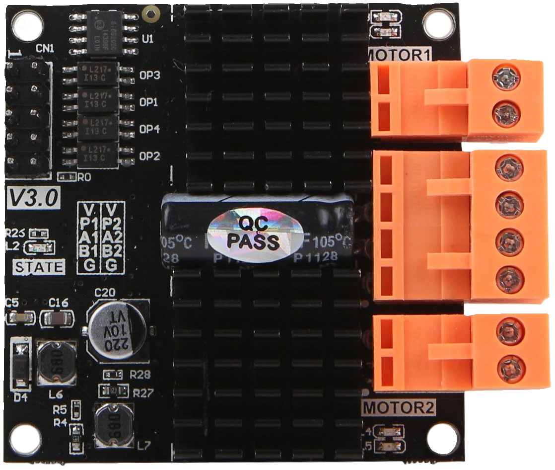
The Dual-Channel DC Motor Driver-12A (Manufacturer Part ID: DFR0601) by DFRobot is a robust motor driver designed to control two DC motors simultaneously. It supports bidirectional control and speed regulation using PWM (Pulse Width Modulation) signals. With a maximum current capacity of 12A per channel, this motor driver is ideal for high-power motor applications.
Explore Projects Built with Dual-Channel DC Motor Driver-12A


Explore Projects Built with Dual-Channel DC Motor Driver-12A
Common Applications
- Robotics and automation systems
- Electric vehicles and carts
- Conveyor belts and industrial machinery
- Remote-controlled cars and boats
- DIY projects requiring precise motor control
Technical Specifications
The following table outlines the key technical details of the DFR0601 motor driver:
| Parameter | Specification |
|---|---|
| Operating Voltage | 6.5V to 30V |
| Maximum Current (per channel) | 12A |
| Control Signal | PWM (Pulse Width Modulation) |
| Logic Voltage | 3.3V to 5V |
| PWM Frequency Range | 0Hz to 20kHz |
| Motor Channels | 2 |
| Dimensions | 60mm x 54mm x 15mm |
| Weight | 30g |
Pin Configuration and Descriptions
The DFR0601 motor driver has the following pin layout:
| Pin Name | Type | Description |
|---|---|---|
| VIN | Power Input | Connect to the motor power supply (6.5V to 30V). |
| GND | Ground | Common ground for the motor driver and control circuit. |
| VCC | Logic Voltage | Connect to the control system's logic voltage (3.3V or 5V). |
| INA1 | Control Input | Input signal to control the direction of Motor A. |
| INB1 | Control Input | Input signal to control the direction of Motor A. |
| PWM1 | Control Input | PWM signal to control the speed of Motor A. |
| INA2 | Control Input | Input signal to control the direction of Motor B. |
| INB2 | Control Input | Input signal to control the direction of Motor B. |
| PWM2 | Control Input | PWM signal to control the speed of Motor B. |
| OUTA+ | Motor Output | Positive terminal for Motor A. |
| OUTA- | Motor Output | Negative terminal for Motor A. |
| OUTB+ | Motor Output | Positive terminal for Motor B. |
| OUTB- | Motor Output | Negative terminal for Motor B. |
Usage Instructions
Connecting the Motor Driver
- Power Supply: Connect the motor power supply to the
VINpin and ground to theGNDpin. Ensure the voltage is within the range of 6.5V to 30V. - Logic Voltage: Connect the
VCCpin to the logic voltage of your control system (3.3V or 5V). - Motor Connections:
- Connect the terminals of Motor A to
OUTA+andOUTA-. - Connect the terminals of Motor B to
OUTB+andOUTB-.
- Connect the terminals of Motor A to
- Control Signals:
- Use the
INA1,INB1, andPWM1pins to control Motor A. - Use the
INA2,INB2, andPWM2pins to control Motor B.
- Use the
Controlling the Motors with an Arduino UNO
Below is an example Arduino sketch to control two DC motors using the DFR0601 motor driver:
// Define motor control pins
#define INA1 7  // Direction control for Motor A
#define INB1 8  // Direction control for Motor A
#define PWM1 9  // Speed control (PWM) for Motor A

#define INA2 4  // Direction control for Motor B
#define INB2 5  // Direction control for Motor B
#define PWM2 6  // Speed control (PWM) for Motor B

void setup() {
  // Set motor control pins as outputs
  pinMode(INA1, OUTPUT);
  pinMode(INB1, OUTPUT);
  pinMode(PWM1, OUTPUT);

  pinMode(INA2, OUTPUT);
  pinMode(INB2, OUTPUT);
  pinMode(PWM2, OUTPUT);
}

void loop() {
  // Example: Run Motor A forward at 50% speed
  digitalWrite(INA1, HIGH);  // Set direction forward
  digitalWrite(INB1, LOW);
  analogWrite(PWM1, 128);    // Set speed (0-255, 128 = 50%)

  // Example: Run Motor B backward at 75% speed
  digitalWrite(INA2, LOW);   // Set direction backward
  digitalWrite(INB2, HIGH);
  analogWrite(PWM2, 192);    // Set speed (0-255, 192 = 75%)

  delay(5000);               // Run for 5 seconds

  // Stop both motors
  analogWrite(PWM1, 0);      // Stop Motor A
  analogWrite(PWM2, 0);      // Stop Motor B
  delay(2000);               // Wait for 2 seconds
}
Important Considerations
- Ensure the motor power supply voltage matches the motor's operating voltage.
- Do not exceed the maximum current rating of 12A per channel.
- Use appropriate heat dissipation methods (e.g., heat sinks) for prolonged high-current operation.
- Always connect the ground (
GND) of the motor driver to the ground of the control system.
Troubleshooting and FAQs
Common Issues
Motors not running:
- Verify that the power supply is connected and within the specified voltage range.
- Check the control signals (INA, INB, and PWM) for proper logic levels.
- Ensure the ground (
GND) is shared between the motor driver and the control system.
Motor running in the wrong direction:
- Swap the
INAandINBsignals for the affected motor. - Verify the wiring of the motor terminals.
- Swap the
Overheating:
- Ensure the current draw of the motors does not exceed 12A per channel.
- Use a heat sink or active cooling if operating at high currents for extended periods.
PWM signal not working:
- Confirm that the PWM frequency is within the supported range (0Hz to 20kHz).
- Check the Arduino code for correct
analogWritevalues (0-255).
FAQs
Q: Can I use this motor driver with a 24V motor?
A: Yes, the motor driver supports operating voltages up to 30V, so it is compatible with 24V motors.
Q: Can I control the motor driver with a Raspberry Pi?
A: Yes, the motor driver accepts 3.3V logic signals, making it compatible with Raspberry Pi GPIO pins.
Q: What happens if the current exceeds 12A?
A: Exceeding the current limit may damage the motor driver. Use a fuse or current-limiting circuit to protect the driver.
Q: Can I control only one motor with this driver?
A: Yes, you can use only one channel (Motor A or Motor B) if your application requires it. Leave the unused channel unconnected.