How to Use KY-016: Examples, Pinouts, and Specs
Introduction
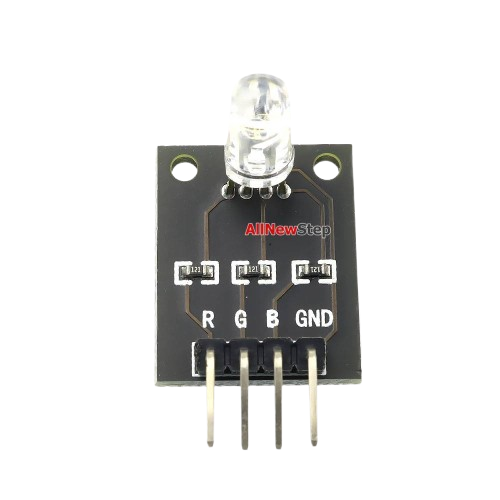
The KY-016 is a versatile color sensor module designed to detect and identify colors. It features an RGB LED and a photodiode, enabling it to measure the intensity of red, green, and blue light reflected from surfaces. This module is widely used in robotics, automation, and DIY electronics projects for applications such as color detection, sorting, and object recognition.
Explore Projects Built with KY-016


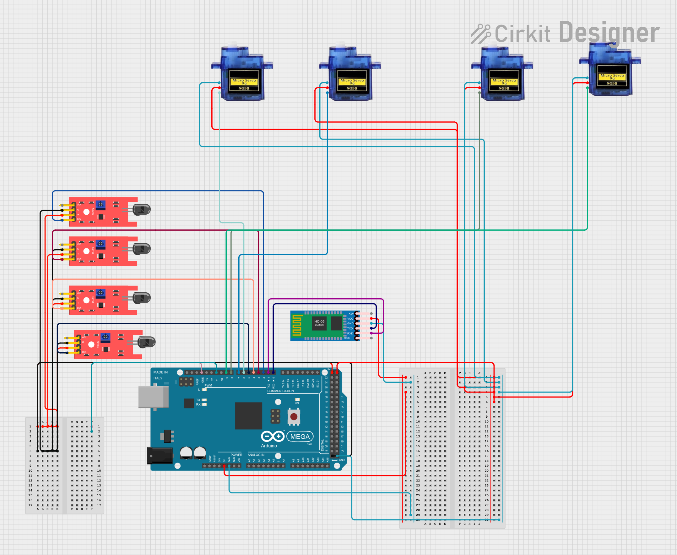
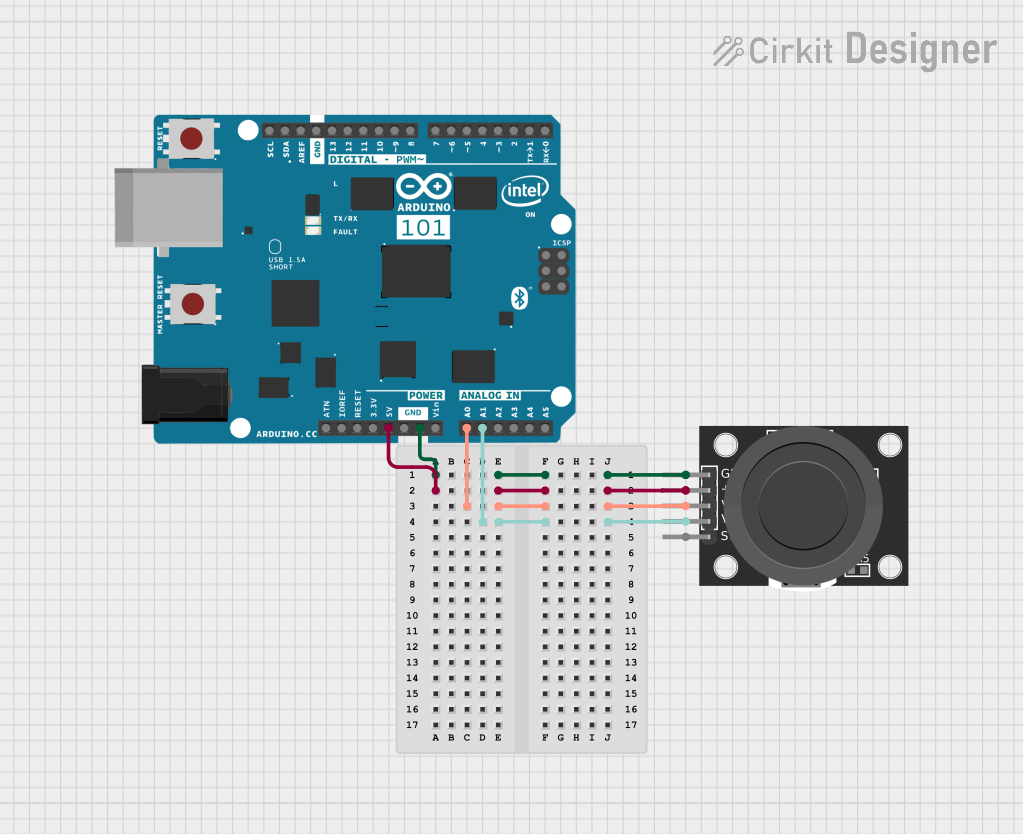
Explore Projects Built with KY-016
Common Applications:
- Color-based object sorting in robotics
- Line-following robots with color-coded paths
- Color recognition in automation systems
- Educational projects and prototyping
Technical Specifications
The KY-016 module is designed for ease of use and compatibility with microcontrollers like Arduino. Below are its key technical details:
Key Specifications:
- Operating Voltage: 3.3V to 5V
- Current Consumption: ~20mA (varies with LED intensity)
- Output Type: Analog signal (proportional to light intensity)
- Detection Range: ~1-5 cm (depending on surface reflectivity)
- Dimensions: 30mm x 15mm x 10mm (approx.)
Pin Configuration:
The KY-016 module has four pins, as described in the table below:
| Pin | Label | Description |
|---|---|---|
| 1 | S | Signal output (analog voltage) |
| 2 | VCC | Power supply (3.3V to 5V) |
| 3 | GND | Ground |
| 4 | LED | Controls the RGB LED (optional, digital pin) |
Usage Instructions
The KY-016 module is straightforward to use in a circuit. Below are the steps and best practices for integrating it into your project:
Connecting the KY-016 to an Arduino UNO:
Wiring:
- Connect the
VCCpin to the 5V pin on the Arduino. - Connect the
GNDpin to the GND pin on the Arduino. - Connect the
Spin to an analog input pin (e.g., A0) on the Arduino. - Optionally, connect the
LEDpin to a digital output pin (e.g., D3) to control the RGB LED.
- Connect the
Arduino Code Example: The following code demonstrates how to read the analog signal from the KY-016 and control the RGB LED.
// KY-016 Color Sensor Example Code
// Connect S to A0, VCC to 5V, GND to GND, and LED to D3 (optional)

const int sensorPin = A0;  // Analog pin connected to KY-016 S pin
const int ledPin = 3;      // Digital pin to control the RGB LED (optional)

void setup() {
  Serial.begin(9600);      // Initialize serial communication
  pinMode(ledPin, OUTPUT); // Set LED pin as output
}

void loop() {
  int sensorValue = analogRead(sensorPin); // Read analog value from sensor

  // Print the sensor value to the Serial Monitor
  Serial.print("Sensor Value: ");
  Serial.println(sensorValue);

  // Optional: Blink the RGB LED based on sensor value
  if (sensorValue > 500) { // Adjust threshold as needed
    digitalWrite(ledPin, HIGH); // Turn on LED
  } else {
    digitalWrite(ledPin, LOW);  // Turn off LED
  }

  delay(100); // Small delay for stability
}
Best Practices:
- Ensure the module is placed close to the surface being measured for accurate readings.
- Avoid exposing the sensor to direct sunlight or strong ambient light, as this may affect accuracy.
- Use a reflective surface for better color detection performance.
- Calibrate the sensor for your specific application by testing and adjusting thresholds in the code.
Troubleshooting and FAQs
Common Issues:
No Output or Incorrect Readings:
- Cause: Loose or incorrect wiring.
- Solution: Double-check all connections and ensure the module is powered correctly.
Inconsistent Sensor Values:
- Cause: Ambient light interference or unstable power supply.
- Solution: Use the module in a controlled lighting environment and ensure a stable power source.
RGB LED Not Working:
- Cause: LED pin not connected or incorrect code.
- Solution: Verify the LED pin connection and ensure the code is correctly configured.
FAQs:
Can the KY-016 detect all colors?
- The KY-016 can detect the intensity of red, green, and blue light, which can be combined to identify a wide range of colors. However, it may struggle with very dark or highly reflective surfaces.
What is the maximum detection range?
- The effective range is approximately 1-5 cm, depending on the reflectivity of the surface.
Can I use the KY-016 with a 3.3V microcontroller?
- Yes, the KY-016 is compatible with both 3.3V and 5V systems.
By following this documentation, you can effectively integrate the KY-016 color sensor module into your projects and troubleshoot common issues with ease.