Cirkit Designer Logo
Cirkit Designer
Your all-in-one circuit design IDE
Home / 
Component Documentation

How to Use Single_Supply_Logic_Level_Converter: Examples, Pinouts, and Specs

Image of Single_Supply_Logic_Level_Converter
Cirkit Designer LogoDesign with Single_Supply_Logic_Level_Converter in Cirkit Designer

Introduction

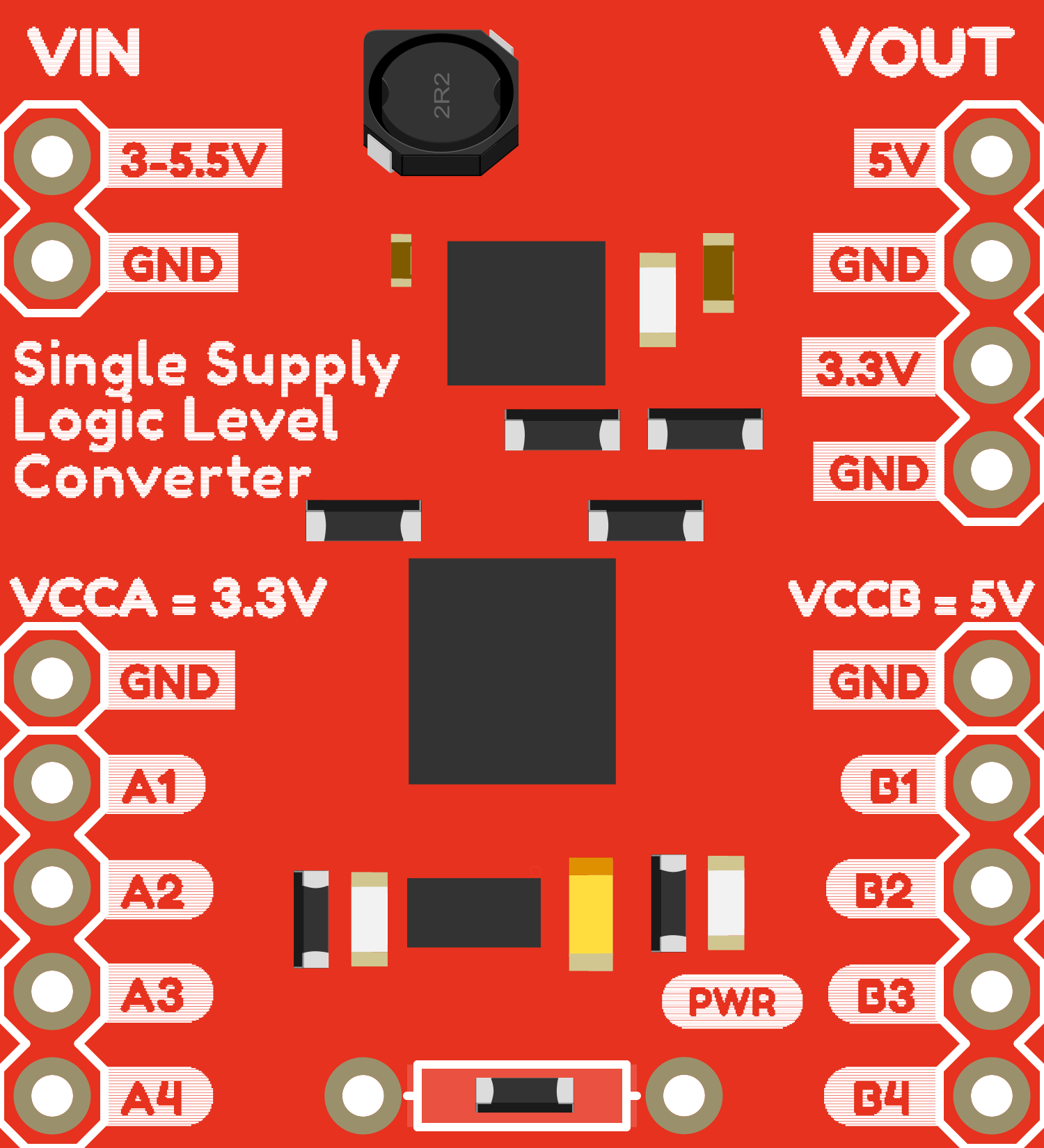
The Single Supply Logic Level Converter is an essential electronic component designed to bridge the gap between devices that operate at different voltage levels. It is commonly used to enable communication between microcontrollers, such as an Arduino UNO, which typically operates at 5V, and peripherals like sensors or modules that may operate at 3.3V. This bidirectional voltage level translation is crucial for protecting low-voltage devices from higher voltage levels and ensuring reliable data transfer.

Explore Projects Built with Single_Supply_Logic_Level_Converter

Use Cirkit Designer to design, explore, and prototype these projects online. Some projects support real-time simulation. Click "Open Project" to start designing instantly!
ESP32 and Logic Level Converter-Based Wi-Fi Controlled Interface
Image of Toshiba AC ESP32 devkit v1: A project utilizing Single_Supply_Logic_Level_Converter in a practical application
This circuit features an ESP32 Devkit V1 microcontroller connected to a Bi-Directional Logic Level Converter, which facilitates voltage level shifting between the ESP32 and external components. The ESP32 is powered through its VIN pin via an alligator clip cable, and the logic level converter is connected to various pins on the ESP32 to manage different voltage levels for communication.
Cirkit Designer LogoOpen Project in Cirkit Designer
Wi-Fi Controlled Device Interface with Wemos D1 Mini and Logic Level Converter
Image of Toshiba AC D1 mini: A project utilizing Single_Supply_Logic_Level_Converter in a practical application
This circuit features a Wemos D1 Mini microcontroller interfaced with a Bi-Directional Logic Level Converter to facilitate communication with a 5V RX/TX module. The level converter ensures proper voltage translation between the 3.3V logic of the Wemos D1 Mini and the 5V logic of the RX/TX module.
Cirkit Designer LogoOpen Project in Cirkit Designer
Multi-Stage Voltage Regulation and Indicator LED Circuit
Image of Subramanyak_Power_Circuit: A project utilizing Single_Supply_Logic_Level_Converter in a practical application
This circuit is designed for power management, featuring buck and boost converters for voltage adjustment, and linear regulators for stable voltage output. It includes LEDs for status indication, and terminal blocks for external connections.
Cirkit Designer LogoOpen Project in Cirkit Designer
12V to 5V Power Supply with LED Indicator and Push Switch
Image of Power Supply LVCO: A project utilizing Single_Supply_Logic_Level_Converter in a practical application
This circuit is a 12V to 5V regulated power supply with an LED indicator. It uses a 5408 diode for reverse polarity protection, an LM340T5 7805 voltage regulator to step down the voltage to 5V, and a push switch to control the LED indicator. The circuit also includes capacitors for filtering and a resistor to limit the current through the LED.
Cirkit Designer LogoOpen Project in Cirkit Designer

Explore Projects Built with Single_Supply_Logic_Level_Converter

Use Cirkit Designer to design, explore, and prototype these projects online. Some projects support real-time simulation. Click "Open Project" to start designing instantly!
Image of Toshiba AC ESP32 devkit v1: A project utilizing Single_Supply_Logic_Level_Converter in a practical application
ESP32 and Logic Level Converter-Based Wi-Fi Controlled Interface
This circuit features an ESP32 Devkit V1 microcontroller connected to a Bi-Directional Logic Level Converter, which facilitates voltage level shifting between the ESP32 and external components. The ESP32 is powered through its VIN pin via an alligator clip cable, and the logic level converter is connected to various pins on the ESP32 to manage different voltage levels for communication.
Cirkit Designer LogoOpen Project in Cirkit Designer
Image of Toshiba AC D1 mini: A project utilizing Single_Supply_Logic_Level_Converter in a practical application
Wi-Fi Controlled Device Interface with Wemos D1 Mini and Logic Level Converter
This circuit features a Wemos D1 Mini microcontroller interfaced with a Bi-Directional Logic Level Converter to facilitate communication with a 5V RX/TX module. The level converter ensures proper voltage translation between the 3.3V logic of the Wemos D1 Mini and the 5V logic of the RX/TX module.
Cirkit Designer LogoOpen Project in Cirkit Designer
Image of Subramanyak_Power_Circuit: A project utilizing Single_Supply_Logic_Level_Converter in a practical application
Multi-Stage Voltage Regulation and Indicator LED Circuit
This circuit is designed for power management, featuring buck and boost converters for voltage adjustment, and linear regulators for stable voltage output. It includes LEDs for status indication, and terminal blocks for external connections.
Cirkit Designer LogoOpen Project in Cirkit Designer
Image of Power Supply LVCO: A project utilizing Single_Supply_Logic_Level_Converter in a practical application
12V to 5V Power Supply with LED Indicator and Push Switch
This circuit is a 12V to 5V regulated power supply with an LED indicator. It uses a 5408 diode for reverse polarity protection, an LM340T5 7805 voltage regulator to step down the voltage to 5V, and a push switch to control the LED indicator. The circuit also includes capacitors for filtering and a resistor to limit the current through the LED.
Cirkit Designer LogoOpen Project in Cirkit Designer

Common Applications and Use Cases

  • Interfacing 3.3V sensors with 5V microcontrollers
  • Connecting 5V peripherals to 3.3V systems
  • Data communication between devices with different operating voltages
  • Prototyping with mixed-voltage systems

Technical Specifications

Key Technical Details

  • Operating Voltage (VCC): 1.8V to 6V
  • Logic Level Input Voltage (VI): 0V to VCC
  • Logic Level Output Voltage (VO): 0V to VCC
  • Continuous Current per Channel: 50 mA
  • Peak Current per Channel: 100 mA
  • Propagation Delay: Typically 6ns (nanoseconds)

Pin Configuration and Descriptions

Pin Number Name Description
1 LV Low-voltage reference (e.g., 3.3V)
2 GND Ground reference
3 HV High-voltage reference (e.g., 5V)
4 LV1 Low-voltage input/output channel 1
5 HV1 High-voltage input/output channel 1
6 LV2 Low-voltage input/output channel 2
7 HV2 High-voltage input/output channel 2

Usage Instructions

How to Use the Component in a Circuit

  1. Connect the GND pin to the common ground of both the high-voltage and low-voltage systems.
  2. Connect the LV pin to the low-voltage power supply (e.g., 3.3V).
  3. Connect the HV pin to the high-voltage power supply (e.g., 5V).
  4. Connect the LVx pins to the low-voltage device's logic pins.
  5. Connect the HVx pins to the high-voltage device's logic pins.

Important Considerations and Best Practices

  • Ensure that the power supplies are stable and within the specified voltage range.
  • Do not exceed the continuous or peak current ratings.
  • Avoid applying signals to the input/output pins before the power supply is stable.
  • Use bypass capacitors close to the power pins to filter out noise and voltage spikes.

Example Connection with Arduino UNO

// Example code for interfacing a 3.3V sensor with a 5V Arduino UNO using the Logic Level Converter

void setup() {
  // Initialize the serial communication at 9600 baud rate
  Serial.begin(9600);
}

void loop() {
  // Read data from the sensor connected to the low-voltage side of the converter
  int sensorValue = analogRead(A0); // Assuming the sensor output is connected to A0

  // Process the sensor data as needed
  // ...

  // Send the processed data to the serial monitor
  Serial.println(sensorValue);

  // Wait for a short period before reading the sensor again
  delay(500);
}

Troubleshooting and FAQs

Common Issues Users Might Face

  • No Signal Conversion: Ensure that the power supplies to both LV and HV are connected and within the correct voltage range.
  • Intermittent Communication: Check for loose connections and ensure that the ground is common between both systems.
  • Device Damage: Verify that the current through the channels does not exceed the specified limits.

Solutions and Tips for Troubleshooting

  • Double-check the wiring, especially the ground and power connections.
  • Use a multimeter to verify the voltage levels at the LV and HV pins.
  • Ensure that the signal lines are not too long, as this can introduce noise and reduce signal integrity.

FAQs

Q: Can the logic level converter be used with I2C or SPI communication?

A: Yes, the logic level converter can be used with both I2C and SPI protocols, as long as the voltage and current specifications are within the limits of the device.

Q: Is it possible to use this converter with more than two channels?

A: This documentation covers a two-channel logic level converter. If more channels are needed, multiple converters can be used or a converter with more channels should be selected.

Q: What happens if I connect the HV pin to a voltage lower than the LV pin?

A: The converter is designed to work with HV being higher than LV. Reversing the voltages may not damage the converter immediately, but it will not function correctly and could potentially lead to damage over time. Always ensure HV is greater than LV.