How to Use SKR 2: Examples, Pinouts, and Specs
Introduction
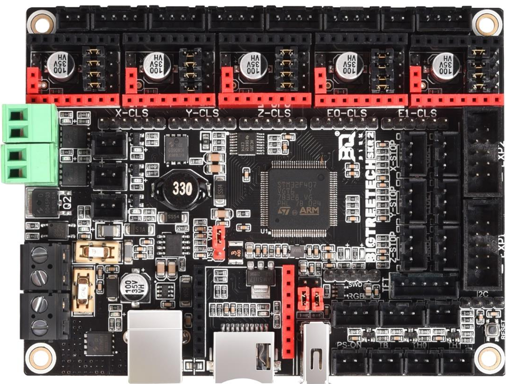
The SKR 2 by BIGTREETECH is a high-performance 32-bit control board designed for 3D printers. Powered by an ARM Cortex-M3 processor, the SKR 2 offers advanced features and capabilities for smooth and precise control of 3D printing operations. It supports a wide range of stepper motor drivers, making it a versatile choice for both hobbyists and professionals.
Explore Projects Built with SKR 2
Explore Projects Built with SKR 2
Common Applications and Use Cases
- 3D printers (FDM, SLA, and other types)
- CNC machines
- Robotics projects requiring precise motor control
- Custom automation systems
The SKR 2 is particularly popular for upgrading older 3D printers to take advantage of modern features like silent stepper drivers, advanced firmware, and improved processing power.
Technical Specifications
Key Technical Details
- Processor: ARM Cortex-M3 (STM32F407 or LPC1769, depending on the version)
- Input Voltage: 12V–24V DC
- Stepper Driver Support: Compatible with TMC, A4988, DRV8825, and other drivers
- Number of Stepper Driver Slots: 5
- Heated Bed Output: Supports high-power heated beds
- Firmware: Compatible with Marlin 2.x and other open-source firmware
- Connectivity: USB, SD card slot, and UART for communication
- Expansion Ports: Multiple ports for BLTouch, filament runout sensors, and other peripherals
- Dimensions: 110mm x 85mm
Pin Configuration and Descriptions
The SKR 2 features multiple connectors and pins for various functions. Below is a summary of the key pin configurations:
Stepper Motor Driver Slots
| Slot Name | Description |
|---|---|
| X | Controls the X-axis stepper motor |
| Y | Controls the Y-axis stepper motor |
| Z | Controls the Z-axis stepper motor |
| E0 | Controls the primary extruder motor |
| E1 | Controls the secondary extruder motor |
Peripheral Connectors
| Connector Name | Description |
|---|---|
| BLTouch | For automatic bed leveling sensors |
| FAN0, FAN1 | For connecting cooling fans |
| HE0, HE1 | For extruder heater cartridges |
| BED | For heated bed power output |
| TFT | For connecting a touchscreen display |
| USB | For USB communication with a computer |
| SD Card Slot | For loading firmware and G-code files |
Power Input
| Pin Name | Description |
|---|---|
| VIN | Main power input (12V–24V DC) |
| GND | Ground connection |
Usage Instructions
How to Use the SKR 2 in a Circuit
- Power Connection: Connect a 12V–24V DC power supply to the VIN and GND terminals. Ensure the power supply can handle the current requirements of your 3D printer.
- Stepper Drivers: Insert compatible stepper drivers (e.g., TMC2209, A4988) into the designated slots. Ensure the orientation matches the board's markings.
- Motor Connections: Connect stepper motors to the X, Y, Z, E0, and E1 motor outputs as needed.
- Heated Bed and Extruder: Connect the heated bed to the BED output and the extruder heater cartridge(s) to HE0 and/or HE1.
- Firmware: Install Marlin 2.x firmware on the board. Use the SD card slot or USB connection to upload the firmware.
- Peripherals: Connect additional peripherals like BLTouch, fans, and filament runout sensors to their respective ports.
Important Considerations and Best Practices
- Stepper Driver Configuration: Configure the stepper driver current and microstepping settings according to your printer's requirements.
- Cooling: Ensure adequate cooling for the board and stepper drivers, especially when running at high currents.
- Firmware Setup: Customize the firmware to match your printer's hardware (e.g., stepper motor steps/mm, bed size, and endstop configuration).
- Wiring: Double-check all connections to avoid short circuits or damage to the board.
Example: Connecting SKR 2 to an Arduino UNO
While the SKR 2 is typically used as a standalone controller, it can communicate with an Arduino UNO via UART for advanced applications. Below is an example Arduino sketch for sending commands to the SKR 2:
#include <SoftwareSerial.h>

// Define RX and TX pins for communication with SKR 2
SoftwareSerial SKRSerial(10, 11); // RX = pin 10, TX = pin 11

void setup() {
  // Initialize serial communication
  Serial.begin(9600); // For debugging with the PC
  SKRSerial.begin(115200); // Communication with SKR 2

  Serial.println("Arduino-SKR 2 Communication Initialized");
}

void loop() {
  // Send a G-code command to the SKR 2
  SKRSerial.println("G28"); // Home all axes
  delay(5000); // Wait 5 seconds before sending the next command

  // Check for responses from the SKR 2
  if (SKRSerial.available()) {
    String response = SKRSerial.readString();
    Serial.println("Response from SKR 2: " + response);
  }
}
Troubleshooting and FAQs
Common Issues and Solutions
Board Not Powering On
- Cause: Incorrect power supply connection or insufficient voltage.
- Solution: Verify the power supply voltage (12V–24V) and ensure proper polarity.
Stepper Motors Not Moving
- Cause: Incorrect stepper driver installation or configuration.
- Solution: Check the orientation of the stepper drivers and ensure the firmware is configured correctly.
Firmware Not Loading
- Cause: Incorrect firmware file or SD card formatting.
- Solution: Ensure the firmware file is named
firmware.binand the SD card is formatted as FAT32.
Overheating Components
- Cause: Insufficient cooling for the board or stepper drivers.
- Solution: Add cooling fans or heatsinks to prevent overheating.
FAQs
Q: Can I use the SKR 2 with TMC2209 drivers?
- A: Yes, the SKR 2 is fully compatible with TMC2209 drivers. Ensure UART mode is configured correctly.
Q: What firmware is recommended for the SKR 2?
- A: Marlin 2.x is the most commonly used firmware for the SKR 2. Other firmware options like Klipper are also supported.
Q: How do I update the firmware?
- A: Copy the firmware file (
firmware.bin) to an SD card, insert it into the SKR 2, and power on the board. The firmware will automatically update.
- A: Copy the firmware file (
Q: Can I connect a touchscreen to the SKR 2?
- A: Yes, the SKR 2 has a dedicated TFT port for connecting BIGTREETECH touchscreens.
This concludes the documentation for the SKR 2. For further assistance, refer to the official BIGTREETECH resources or community forums.