How to Use SyRen 10A 6V-24V Regenerative Motor Driver: Examples, Pinouts, and Specs
Introduction
The SyRen 10A 6V-24V Regenerative Motor Driver (Manufacturer Part ID: SyRen 10) by Dimension Engineering is a robust and versatile motor driver designed for controlling DC motors. It supports a wide operating voltage range of 6V to 24V and can handle continuous currents of up to 10A. One of its standout features is regenerative braking, which allows energy recovery during motor deceleration, improving efficiency in battery-powered systems.
This motor driver is ideal for applications such as:
- Robotics and automation systems
- Electric vehicles and carts
- Conveyor belts and industrial machinery
- Remote-controlled vehicles and boats
Explore Projects Built with SyRen 10A 6V-24V Regenerative Motor Driver


Explore Projects Built with SyRen 10A 6V-24V Regenerative Motor Driver
Technical Specifications
Below are the key technical details of the SyRen 10 motor driver:
| Parameter | Value |
|---|---|
| Operating Voltage Range | 6V to 24V |
| Continuous Current | 10A |
| Peak Current | 15A (for short durations) |
| Control Modes | Analog, R/C, Serial, Packetized |
| Regenerative Braking | Yes |
| Dimensions | 1.8" x 1.3" x 0.5" (45mm x 33mm x 13mm) |
| Weight | 0.5 oz (14g) |
| Operating Temperature | -40°C to 85°C |
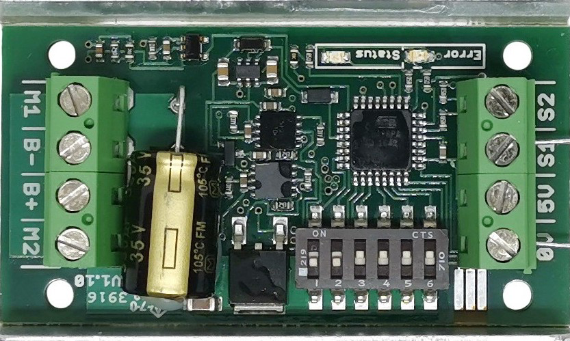
Pin Configuration and Descriptions
The SyRen 10 motor driver has the following pin layout:
| Pin Name | Description |
|---|---|
| VIN | Input voltage (6V to 24V). Connect to the positive terminal of the power supply. |
| GND | Ground connection. Connect to the negative terminal of the power supply. |
| M1A | Motor terminal A. Connect to one terminal of the DC motor. |
| M1B | Motor terminal B. Connect to the other terminal of the DC motor. |
| S1 | Signal input 1. Used for control signals in various modes. |
| S2 | Signal input 2. Used for control signals in various modes. |
| 5V | 5V output. Can be used to power external logic circuits (max 50mA). |
Usage Instructions
How to Use the SyRen 10 in a Circuit
- Power Supply: Connect a DC power supply (6V to 24V) to the VIN and GND pins. Ensure the power supply can provide sufficient current for your motor.
- Motor Connection: Connect the DC motor terminals to the M1A and M1B pins. Reversing these connections will reverse the motor's direction.
- Control Signals: Depending on the control mode, connect the appropriate signals to the S1 and S2 pins:
- Analog Mode: Use a potentiometer or analog voltage source.
- R/C Mode: Connect to an R/C receiver.
- Serial Mode: Use a microcontroller or PC to send serial commands.
- Regenerative Braking: Ensure the power supply can handle regenerative currents if braking is used.
Important Considerations and Best Practices
- Heat Dissipation: The SyRen 10 is designed to handle 10A continuously, but ensure adequate ventilation or heat sinking for high-current applications.
- Power Supply Selection: Use a power supply with sufficient current capacity and ensure it can handle regenerative energy.
- Control Mode Configuration: Configure the DIP switches on the board to select the desired control mode. Refer to the manufacturer's manual for detailed DIP switch settings.
- Arduino Integration: The SyRen 10 can be controlled via serial communication with an Arduino. Below is an example code snippet for controlling the motor driver in serial mode.
Example Arduino Code
#include <SoftwareSerial.h>

// Define the pins for SoftwareSerial communication
#define TX_PIN 10  // Arduino TX pin connected to SyRen S1
#define RX_PIN 11  // Arduino RX pin (not used in this example)

SoftwareSerial SyRenSerial(TX_PIN, RX_PIN);

void setup() {
  SyRenSerial.begin(9600); // Initialize serial communication at 9600 baud
  delay(100);              // Allow time for the SyRen to initialize
}

void loop() {
  // Send a command to set motor speed (range: 0 to 127 for forward, 128 to 255 for reverse)
  SyRenSerial.write(64); // Example: Set motor to half-speed forward
  delay(2000);           // Run motor for 2 seconds

  SyRenSerial.write(0);  // Stop the motor
  delay(1000);           // Wait for 1 second

  SyRenSerial.write(192); // Set motor to half-speed reverse
  delay(2000);            // Run motor for 2 seconds

  SyRenSerial.write(0);   // Stop the motor
  delay(1000);            // Wait for 1 second
}
Note: Ensure the SyRen 10 is configured for serial mode using the DIP switches. The motor speed range is 0-127 for forward and 128-255 for reverse.
Troubleshooting and FAQs
Common Issues and Solutions
Motor Not Running:
- Verify the power supply voltage and current ratings.
- Check the motor connections to M1A and M1B.
- Ensure the control signals are correctly configured for the selected mode.
Overheating:
- Ensure proper ventilation or add a heat sink if the driver is operating near its maximum current rating.
- Reduce the motor load if possible.
Erratic Motor Behavior:
- Check for noise or interference in the control signals.
- Verify the DIP switch settings for the selected control mode.
Regenerative Braking Issues:
- Ensure the power supply can handle regenerative currents. Use a battery or a power supply with sufficient energy absorption capability.
FAQs
Q: Can the SyRen 10 drive two motors?
A: No, the SyRen 10 is a single-channel motor driver and can control only one motor.
Q: What happens if the input voltage exceeds 24V?
A: Exceeding 24V can damage the motor driver. Always ensure the input voltage is within the specified range.
Q: Can I use the 5V output to power my Arduino?
A: Yes, but the 5V output is limited to 50mA. Ensure your Arduino's power requirements do not exceed this limit.
Q: How do I reverse the motor direction?
A: You can reverse the motor direction by swapping the M1A and M1B connections or by sending reverse commands in serial mode.
By following this documentation, you can effectively integrate the SyRen 10 motor driver into your projects and troubleshoot common issues with ease.