
How to Use Darlington Driver: Examples, Pinouts, and Specs
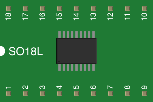
 Design with Darlington Driver in Cirkit Designer
Introduction
A Darlington Driver is a transistor configuration that combines two bipolar junction transistors (BJTs) in a cascaded arrangement to achieve a very high current gain. This configuration allows the Darlington Driver to amplify small input currents into much larger output currents, making it suitable for driving high-current loads. It is commonly used in applications such as motor control, relay driving, LED arrays, and other switching tasks where a single transistor cannot provide sufficient current.
Explore Projects Built with Darlington Driver
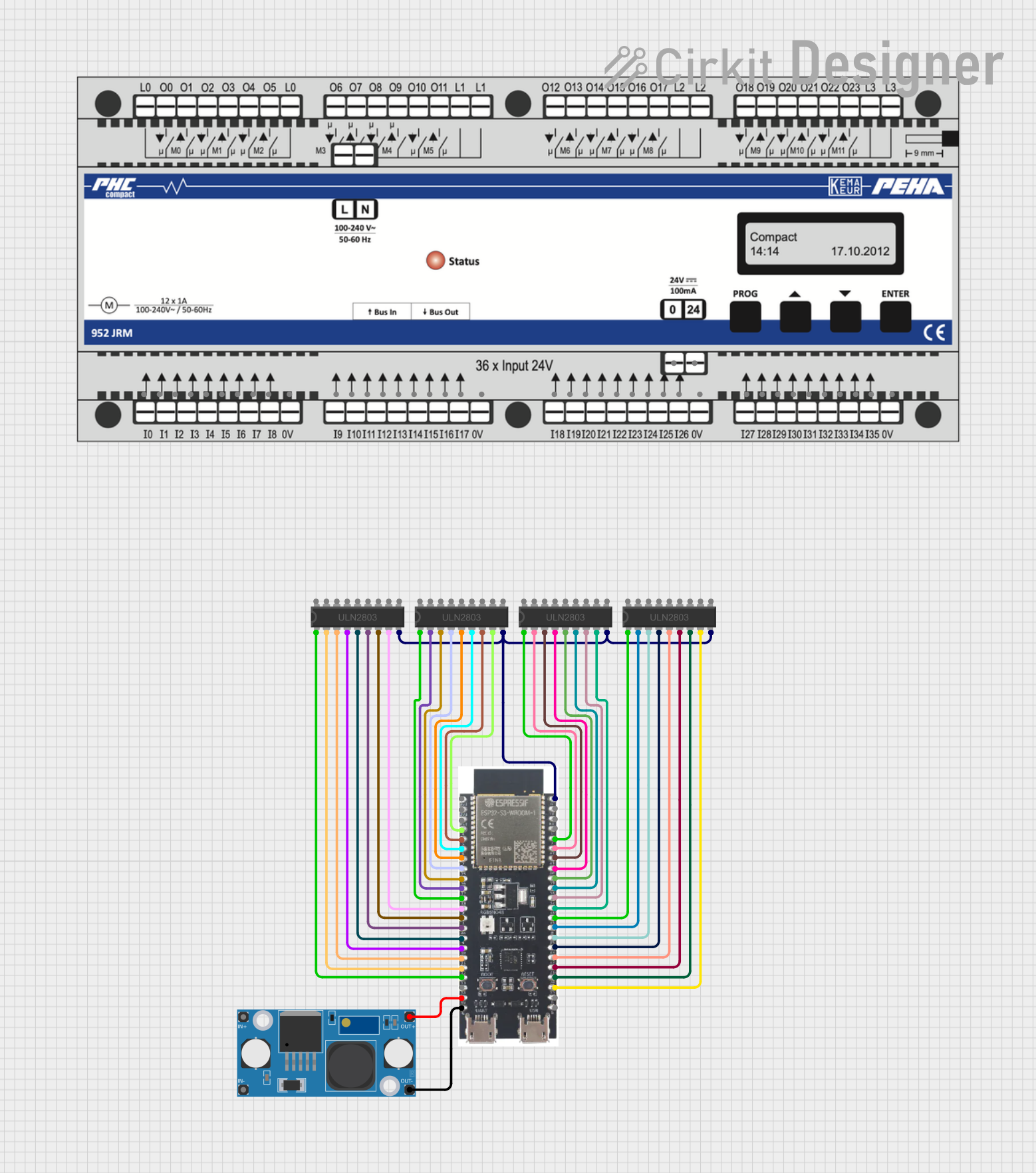 Open Project in Cirkit Designer
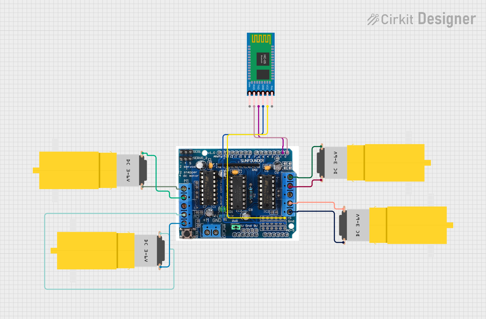 Open Project in Cirkit Designer
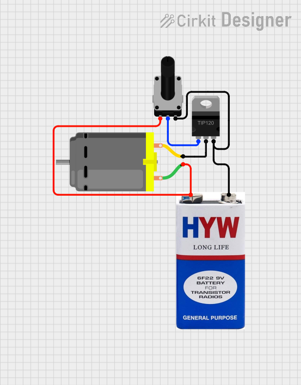 Open Project in Cirkit Designer
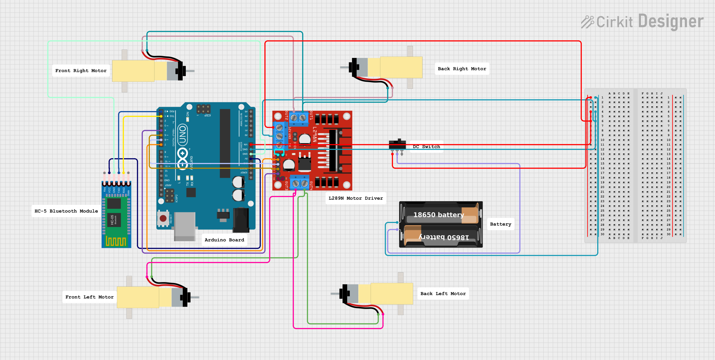 Open Project in Cirkit Designer
Explore Projects Built with Darlington Driver
Open Project in Cirkit DesignerOpen Project in Cirkit DesignerOpen Project in Cirkit DesignerOpen Project in Cirkit DesignerCommon Applications:
- Motor control circuits
- Relay and solenoid driving
- LED matrix and display control
- High-current switching applications
- Signal amplification in control systems
Technical Specifications
Key Technical Details:
- Voltage Rating (Vce): Typically up to 100V (varies by model)
- Current Rating (Ic): Up to several amps (e.g., 500mA to 5A)
- Current Gain (hFE): Typically 1000 to 10,000
- Input Voltage (Vbe): ~1.2V to 2.5V (due to two base-emitter junctions)
- Power Dissipation: Depends on the package and cooling, typically 1W to 2W
- Package Types: TO-220, DIP, or SMD packages
Pin Configuration and Descriptions:
Below is the pin configuration for a common Darlington Driver IC, such as the ULN2003A (a popular Darlington array IC):
| Pin Number | Pin Name | Description |
|---|---|---|
| 1-7 | Input 1-7 | Inputs for each Darlington pair. A small current here controls the corresponding output. |
| 8 | GND | Ground pin for the IC. Connect to the circuit's ground. |
| 9 | COM | Common pin for freewheeling diodes. Connect to the positive supply for inductive loads. |
| 10-16 | Output 1-7 | Outputs for each Darlington pair. These pins drive the connected loads. |
Note: The pin configuration may vary for discrete Darlington transistors or other Darlington ICs. Always refer to the specific datasheet.
Usage Instructions
How to Use the Component in a Circuit:
- Input Signal: Connect the input signal to the base of the Darlington Driver (or the input pin in the case of an IC). Ensure the input voltage is sufficient to turn on the transistors (typically 1.2V to 2.5V).
- Load Connection: Connect the load (e.g., motor, relay, or LED array) to the output pin or collector of the Darlington Driver. The other end of the load should connect to the positive supply voltage.
- Ground Connection: Ensure the emitter (or GND pin in the case of an IC) is connected to the circuit's ground.
- Freewheeling Diode (for Inductive Loads): If driving inductive loads like motors or relays, connect a freewheeling diode across the load to protect the Darlington Driver from voltage spikes.
Important Considerations:
- Heat Dissipation: Darlington Drivers can generate significant heat when driving high-current loads. Use a heatsink or proper cooling if necessary.
- Input Voltage: Ensure the input voltage is within the specified range to avoid damaging the component.
- Current Limiting: Use a base resistor or current-limiting resistor to prevent excessive current through the input.
- Inductive Loads: Always use a freewheeling diode to protect the driver from back EMF generated by inductive loads.
Example: Using ULN2003A with Arduino UNO
Below is an example of how to use the ULN2003A Darlington Driver IC to control a 12V DC motor with an Arduino UNO:
// Example: Controlling a 12V DC motor using ULN2003A and Arduino UNO

const int motorPin = 3; // Arduino pin connected to ULN2003A input pin 1

void setup() {
  pinMode(motorPin, OUTPUT); // Set motorPin as an output
}

void loop() {
  digitalWrite(motorPin, HIGH); // Turn on the motor
  delay(2000);                 // Keep the motor on for 2 seconds
  digitalWrite(motorPin, LOW);  // Turn off the motor
  delay(2000);                 // Keep the motor off for 2 seconds
}
Note: Connect the motor to the corresponding output pin of the ULN2003A. The COM pin should be connected to the 12V supply, and the GND pin should be connected to the Arduino's ground.
Troubleshooting and FAQs
Common Issues:
Component Overheating:
- Cause: Excessive current through the Darlington Driver or insufficient cooling.
- Solution: Use a heatsink or reduce the load current.
Load Not Turning On:
- Cause: Insufficient input voltage or incorrect wiring.
- Solution: Check the input voltage and ensure proper connections.
Voltage Drop Across the Driver:
- Cause: The Darlington configuration introduces a voltage drop (~1.2V to 2.5V).
- Solution: Account for this voltage drop when designing the circuit.
Damage to the Driver:
- Cause: Back EMF from inductive loads or exceeding voltage/current ratings.
- Solution: Use a freewheeling diode for inductive loads and ensure the ratings are not exceeded.
FAQs:
Q: Can I use a Darlington Driver for PWM control?
A: Yes, Darlington Drivers can handle PWM signals, but ensure the switching frequency is within the component's capabilities.Q: Why is there a voltage drop across the Darlington Driver?
A: The voltage drop is due to the two base-emitter junctions in the Darlington configuration. This is a characteristic of the design.Q: Can I use a Darlington Driver with a 3.3V microcontroller?
A: Yes, but ensure the input voltage is sufficient to turn on the transistors. Some Darlington Drivers may require a higher input voltage.
By following this documentation, you can effectively use a Darlington Driver in your electronic projects!