How to Use TeenzyLC: Examples, Pinouts, and Specs
Introduction
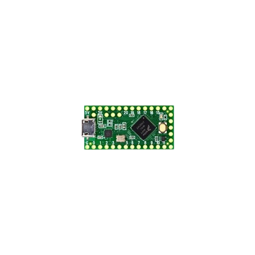
The TeenzyLC is a compact, low-power microcontroller board designed for embedded applications. It features a range of digital and analog I/O pins, making it highly versatile for various projects. Its small form factor and energy efficiency make it ideal for applications such as IoT devices, robotics, wearable technology, and sensor-based systems. The board is compatible with a wide array of sensors and modules, providing flexibility for both hobbyists and professionals.
Common applications of the TeenzyLC include:
- IoT (Internet of Things) devices
- Robotics and automation systems
- Data acquisition and logging
- Wearable technology
- Prototyping and educational projects
Explore Projects Built with TeenzyLC
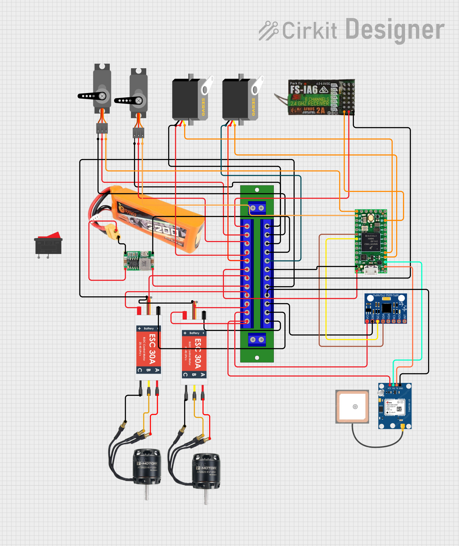

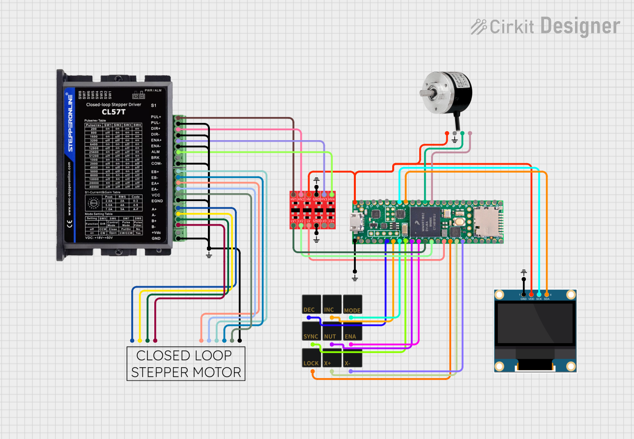
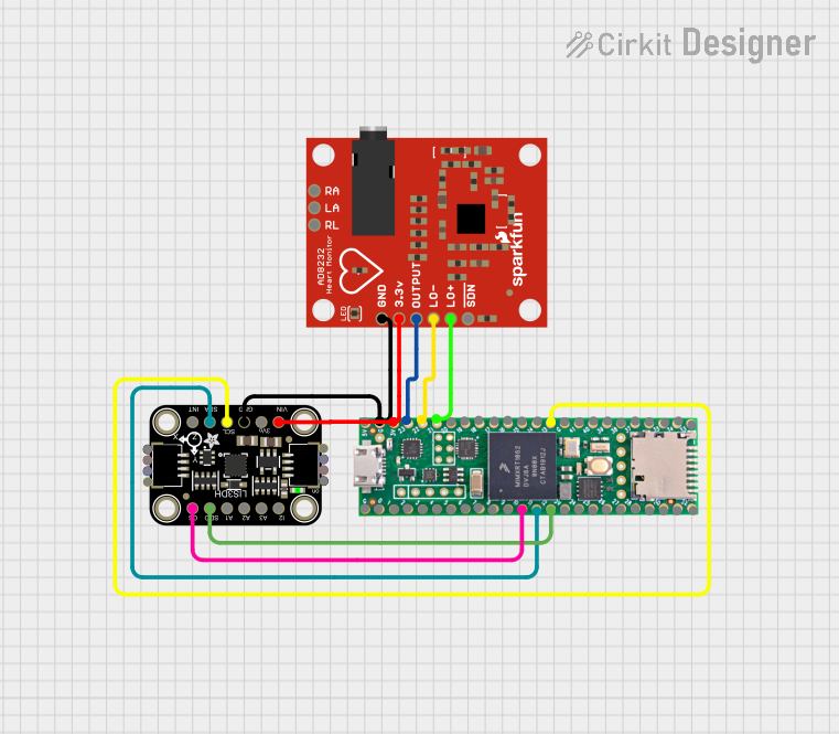
Explore Projects Built with TeenzyLC
Technical Specifications
The following are the key technical details of the TeenzyLC microcontroller board:
| Specification | Details |
|---|---|
| Microcontroller | ARM Cortex-M0+ 32-bit processor |
| Clock Speed | 48 MHz |
| Flash Memory | 62 KB |
| RAM | 8 KB |
| Operating Voltage | 3.3V (all I/O pins are 3.3V tolerant) |
| Input Voltage (VIN) | 3.6V to 6.0V |
| Digital I/O Pins | 25 pins (with 13 PWM-capable pins) |
| Analog Input Pins | 12 pins (10-bit resolution) |
| Communication Interfaces | UART, I2C, SPI |
| USB | Micro-USB for programming and power supply |
| Power Consumption | Low-power design, suitable for battery-powered applications |
| Dimensions | 1.4 x 0.7 inches (35.56 x 17.78 mm) |
Pin Configuration and Descriptions
The TeenzyLC has a total of 25 digital I/O pins, including analog inputs and PWM outputs. Below is the pin configuration:
| Pin | Type | Description |
|---|---|---|
| VIN | Power Input | Input voltage (3.6V to 6.0V) |
| GND | Ground | Ground connection |
| 0-12 | Digital I/O | General-purpose digital I/O pins (PWM available on select pins) |
| 13-23 | Analog Input | 12 analog input pins with 10-bit resolution |
| AREF | Analog Ref. | Reference voltage for analog inputs |
| SDA | I2C Data | Data line for I2C communication |
| SCL | I2C Clock | Clock line for I2C communication |
| TX/RX | UART | Serial communication pins (TX for transmit, RX for receive) |
| MOSI | SPI Data Out | Master Out Slave In for SPI communication |
| MISO | SPI Data In | Master In Slave Out for SPI communication |
| SCK | SPI Clock | Clock signal for SPI communication |
| USB | USB Port | Micro-USB port for programming and power supply |
Usage Instructions
How to Use the TeenzyLC in a Circuit
- Powering the Board: Connect the VIN pin to a power source (3.6V to 6.0V) or use the Micro-USB port for power and programming.
- Connecting I/O Devices: Use the digital and analog pins to connect sensors, actuators, or other peripherals. Ensure that all connected devices operate at 3.3V logic levels.
- Programming the Board: Install the Arduino IDE and the Teensyduino add-on to program the board. Select "Teensy LC" as the board type in the IDE.
- Uploading Code: Write your code in the Arduino IDE, connect the board via USB, and upload the code.
Important Considerations and Best Practices
- Voltage Levels: All I/O pins operate at 3.3V. Connecting 5V devices directly to the pins may damage the board.
- Power Supply: Ensure a stable power supply to avoid unexpected resets or malfunctions.
- Pin Usage: Avoid using the same pin for multiple functions simultaneously (e.g., digital I/O and PWM).
- Libraries: Use compatible libraries for sensors and modules to simplify development.
Example Code for Arduino UNO Compatibility
The following example demonstrates how to read an analog sensor value and control an LED using the TeenzyLC:
// Define pin numbers
const int analogPin = A0; // Analog sensor connected to pin A0
const int ledPin = 13;    // LED connected to digital pin 13

void setup() {
  pinMode(ledPin, OUTPUT); // Set LED pin as output
  Serial.begin(9600);      // Initialize serial communication
}

void loop() {
  int sensorValue = analogRead(analogPin); // Read analog sensor value
  Serial.println(sensorValue);             // Print sensor value to Serial Monitor

  // Map sensor value to PWM range (0-255) and write to LED
  int ledBrightness = map(sensorValue, 0, 1023, 0, 255);
  analogWrite(ledPin, ledBrightness);

  delay(100); // Small delay for stability
}
Troubleshooting and FAQs
Common Issues and Solutions
Board Not Recognized by Computer:
- Ensure the USB cable is functional and supports data transfer.
- Verify that the correct board type ("Teensy LC") is selected in the Arduino IDE.
- Install or update the Teensyduino add-on.
Code Upload Fails:
- Check the USB connection and ensure the board is in programming mode.
- Press the reset button on the board to reinitialize the bootloader.
I/O Pins Not Working:
- Confirm that the connected devices are operating at 3.3V logic levels.
- Check for loose or incorrect wiring.
Power Issues:
- Use a stable power source within the specified voltage range (3.6V to 6.0V).
- Avoid powering high-current devices directly from the board.
FAQs
Q: Can the TeenzyLC handle 5V logic devices?
A: No, the I/O pins are 3.3V tolerant. Use a level shifter to interface with 5V devices.
Q: What is the maximum current output of the I/O pins?
A: Each I/O pin can source or sink up to 10mA. Exceeding this limit may damage the pin.
Q: Is the board compatible with Arduino libraries?
A: Yes, most Arduino libraries are compatible with the TeenzyLC when using the Teensyduino add-on.
Q: Can I power the board using a battery?
A: Yes, you can use a battery within the voltage range of 3.6V to 6.0V connected to the VIN pin.
By following this documentation, you can effectively utilize the TeenzyLC for your embedded projects.