
How to Use RS26 4 Position Rotary Band Switch: Examples, Pinouts, and Specs
 Design with RS26 4 Position Rotary Band Switch in Cirkit Designer
Introduction
The RS26 4 Position Rotary Band Switch is a versatile rotary switch designed to allow the selection of one of four different positions or circuits. This component is commonly used in audio equipment, control panels, and other applications where switching between multiple settings or functions is required. Its robust design and reliable operation make it a popular choice for both hobbyists and professionals.
Explore Projects Built with RS26 4 Position Rotary Band Switch
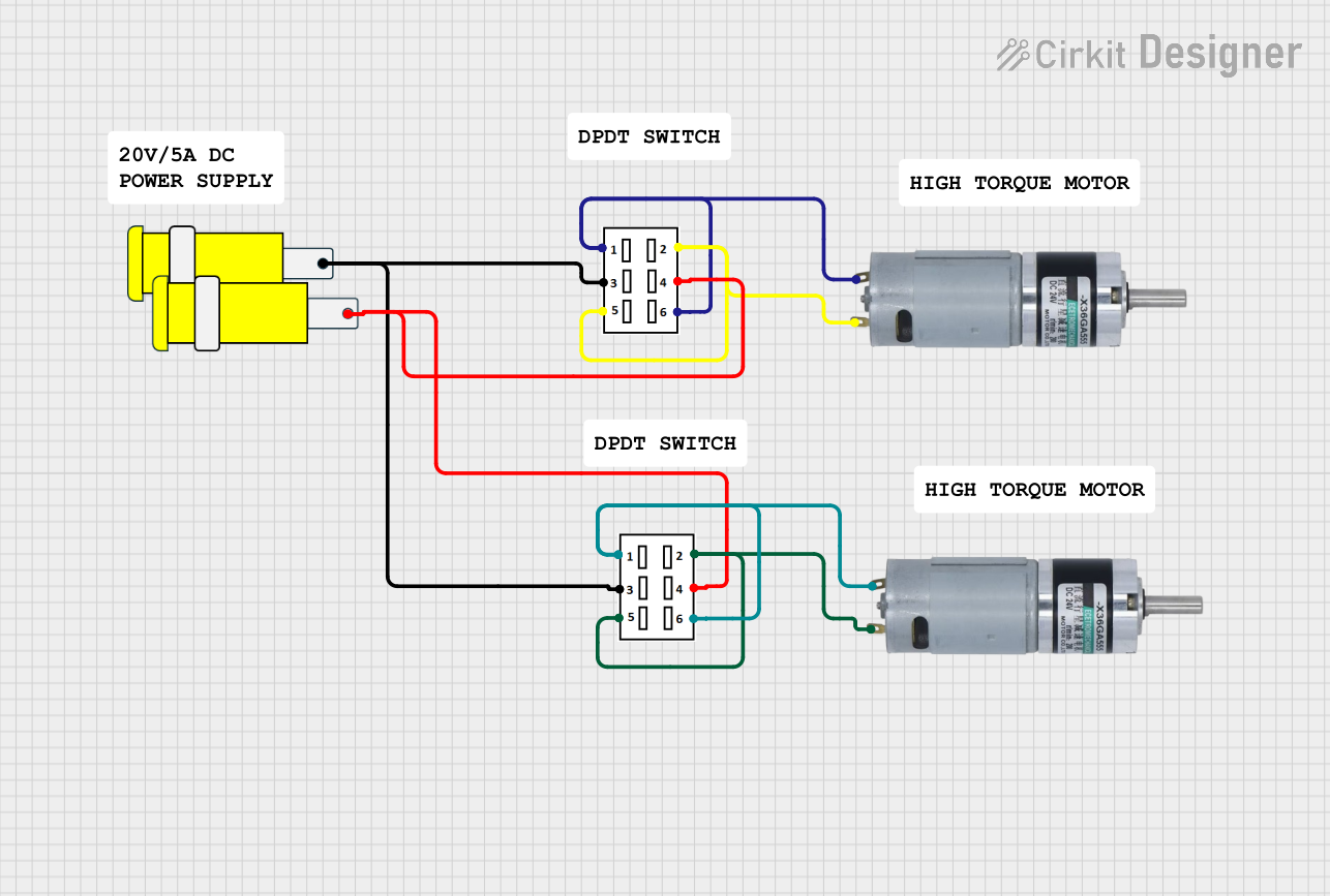 Open Project in Cirkit Designer
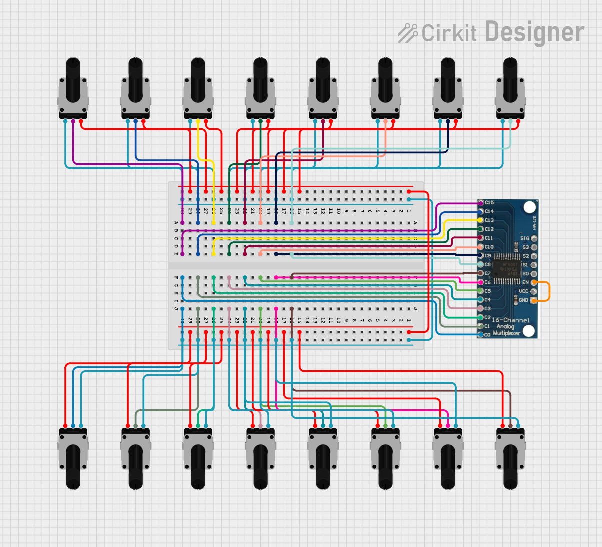 Open Project in Cirkit Designer
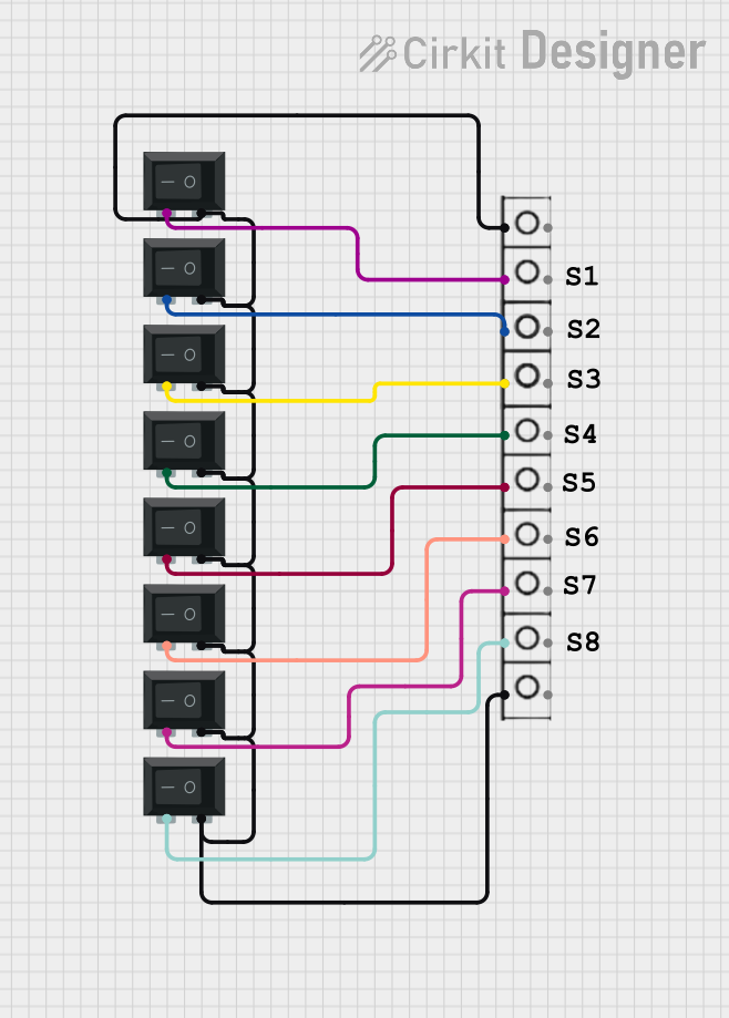 Open Project in Cirkit Designer
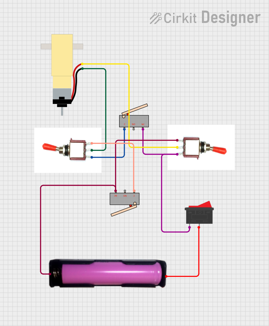 Open Project in Cirkit Designer
Explore Projects Built with RS26 4 Position Rotary Band Switch
Open Project in Cirkit DesignerOpen Project in Cirkit DesignerOpen Project in Cirkit DesignerOpen Project in Cirkit DesignerCommon Applications
- Audio equipment for selecting input sources or equalizer settings
- Control panels for switching between operational modes
- Test and measurement devices for selecting ranges or configurations
- DIY electronics projects requiring multi-position switching
Technical Specifications
The RS26 4 Position Rotary Band Switch is designed for durability and ease of use. Below are its key technical details:
Key Specifications
| Parameter | Value |
|---|---|
| Number of Positions | 4 |
| Switching Mechanism | Rotary |
| Contact Rating | 0.3A at 125V AC / 0.5A at 12V DC |
| Insulation Resistance | ≥ 100 MΩ at 500V DC |
| Contact Resistance | ≤ 50 mΩ |
| Operating Temperature | -25°C to +85°C |
| Mechanical Life | 10,000 cycles |
Pin Configuration and Descriptions
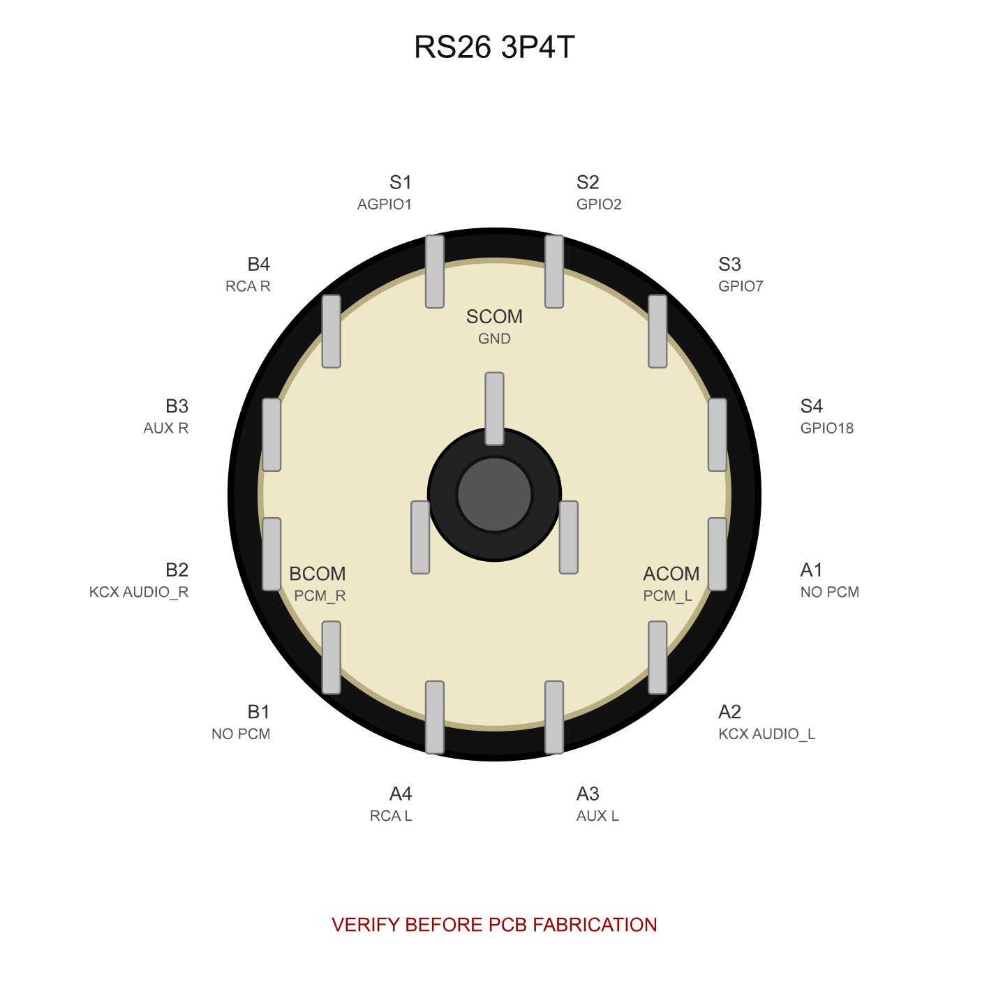
The RS26 switch typically has a central common pin and four output pins corresponding to the four positions. The pin configuration is as follows:
| Pin Number | Description |
|---|---|
| 1 | Output for Position 1 |
| 2 | Output for Position 2 |
| 3 | Output for Position 3 |
| 4 | Output for Position 4 |
| C | Common pin (connected to the input) |
Usage Instructions
How to Use the RS26 in a Circuit
- Identify the Pins: Locate the common pin (C) and the four output pins (1, 2, 3, 4) on the switch.
- Connect the Common Pin: Connect the common pin to the input signal or voltage source.
- Connect the Output Pins: Connect each output pin to the desired circuit or load corresponding to the switch positions.
- Mount the Switch: Secure the switch to your project enclosure or panel using the mounting hardware provided.
- Test the Circuit: Rotate the switch to each position and verify that the correct circuit is activated.
Important Considerations
- Voltage and Current Ratings: Ensure that the voltage and current in your circuit do not exceed the switch's rated values (0.3A at 125V AC or 0.5A at 12V DC).
- Debouncing: If the switch is used in a digital circuit, consider implementing debouncing to avoid erratic behavior when switching positions.
- Mechanical Stress: Avoid applying excessive force when rotating the switch to prevent damage to the internal mechanism.
Example: Connecting to an Arduino UNO
The RS26 can be used with an Arduino UNO to detect the selected position. Below is an example code snippet:
// RS26 Rotary Switch Example with Arduino UNO
// Connect the common pin (C) to GND and the output pins (1, 2, 3, 4) to digital pins 2-5.

const int switchPins[] = {2, 3, 4, 5}; // Pins connected to the RS26 outputs
int currentPosition = -1; // Variable to store the current position

void setup() {
  Serial.begin(9600); // Initialize serial communication
  for (int i = 0; i < 4; i++) {
    pinMode(switchPins[i], INPUT_PULLUP); // Set switch pins as input with pull-up resistors
  }
}

void loop() {
  for (int i = 0; i < 4; i++) {
    if (digitalRead(switchPins[i]) == LOW) {
      // Check if the switch is in position i (active LOW)
      if (currentPosition != i) {
        // Update position only if it has changed
        currentPosition = i;
        Serial.print("Switch Position: ");
        Serial.println(i + 1); // Print the current position (1-based index)
      }
    }
  }
}
Notes:
- Ensure the common pin (C) is connected to the Arduino's GND.
- The output pins (1, 2, 3, 4) should be connected to digital pins on the Arduino.
Troubleshooting and FAQs
Common Issues
Switch Not Working in Circuit
- Cause: Incorrect wiring or loose connections.
- Solution: Double-check the pin connections and ensure the common pin is properly connected.
Erratic Behavior in Digital Circuits
- Cause: Switch bouncing.
- Solution: Implement software or hardware debouncing techniques.
Switch Feels Stiff or Difficult to Rotate
- Cause: Mechanical wear or debris in the mechanism.
- Solution: Clean the switch with compressed air or contact cleaner. Avoid excessive force.
Incorrect Position Detection with Arduino
- Cause: Pull-up resistors not enabled or incorrect pin configuration.
- Solution: Verify the Arduino code and ensure pull-up resistors are enabled.
FAQs
Q: Can the RS26 switch handle high-power applications?
A: No, the RS26 is designed for low-power applications with a maximum rating of 0.3A at 125V AC or 0.5A at 12V DC.
Q: Can I use the RS26 switch in outdoor environments?
A: The RS26 is not weatherproof. If outdoor use is required, ensure it is housed in a weather-resistant enclosure.
Q: How do I extend the life of the switch?
A: Operate the switch within its rated specifications and avoid excessive mechanical stress. Regular cleaning can also help maintain performance.
Q: Can I use the RS26 switch with more than four circuits?
A: No, the RS26 is specifically designed for four positions. For more circuits, consider a rotary switch with additional positions.