Cirkit Designer Logo
Cirkit Designer
Your all-in-one circuit design IDE
Home / 
Component Documentation

How to Use verter_usb: Examples, Pinouts, and Specs

Image of verter_usb
Cirkit Designer LogoDesign with verter_usb in Cirkit Designer

Introduction

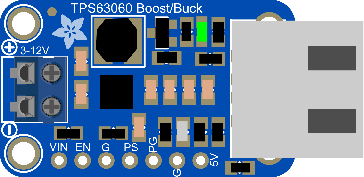
The Verter_USB is a versatile DC-DC converter module that takes power from a USB source and provides a regulated and adjustable voltage output. This component is ideal for powering electronic projects that require a stable voltage supply different from the standard 5V provided by USB ports. Common applications include battery charging, powering small motors, or providing an adjustable supply for prototyping and testing circuits.

Explore Projects Built with verter_usb

Use Cirkit Designer to design, explore, and prototype these projects online. Some projects support real-time simulation. Click "Open Project" to start designing instantly!
Battery-Powered USB Charger with LED Indicator and DC Motor
Image of Copy of Hand Crank mobile charger : A project utilizing verter_usb in a practical application
This circuit converts AC power to DC using a bridge rectifier and regulates the voltage to 5V with a 7805 voltage regulator. It powers a USB port and indicates power status with an LED, while also providing a charging interface through a multi-charging cable.
Cirkit Designer LogoOpen Project in Cirkit Designer
Dual Hub Motor Control System with USB to TTL Interface and Relay Switching
Image of Hub Motor & servo motor Connection: A project utilizing verter_usb in a practical application
This circuit is designed to control two hub motors using a HUB driver, powered by a DC-DC converter and a power module. The USB to TTL converter allows for communication with the HUB driver, and a 5V relay module is used to switch the motors on and off.
Cirkit Designer LogoOpen Project in Cirkit Designer
Pushbutton-Controlled Interface with 40-Pin Connector and UBS Power Supply
Image of connect 4: A project utilizing verter_usb in a practical application
This circuit consists of a 40-pin connector interfacing with four pushbuttons and a UBS power supply. The pushbuttons are used as inputs to the connector, which then relays the signals to other components or systems. The UBS power supply provides the necessary 24V power to the pushbuttons and the common ground for the circuit.
Cirkit Designer LogoOpen Project in Cirkit Designer
USB Power Supply with Overcurrent Protection
Image of USB Charging port: A project utilizing verter_usb in a practical application
This circuit is designed to step down voltage from a 12V battery to a lower voltage suitable for USB devices. It includes a buck converter connected to the battery through a fuse and fuse holder for overcurrent protection. The output of the buck converter is connected to a USB female port, providing a regulated power supply for USB-powered devices.
Cirkit Designer LogoOpen Project in Cirkit Designer

Explore Projects Built with verter_usb

Use Cirkit Designer to design, explore, and prototype these projects online. Some projects support real-time simulation. Click "Open Project" to start designing instantly!
Image of Copy of Hand Crank mobile charger : A project utilizing verter_usb in a practical application
Battery-Powered USB Charger with LED Indicator and DC Motor
This circuit converts AC power to DC using a bridge rectifier and regulates the voltage to 5V with a 7805 voltage regulator. It powers a USB port and indicates power status with an LED, while also providing a charging interface through a multi-charging cable.
Cirkit Designer LogoOpen Project in Cirkit Designer
Image of Hub Motor & servo motor Connection: A project utilizing verter_usb in a practical application
Dual Hub Motor Control System with USB to TTL Interface and Relay Switching
This circuit is designed to control two hub motors using a HUB driver, powered by a DC-DC converter and a power module. The USB to TTL converter allows for communication with the HUB driver, and a 5V relay module is used to switch the motors on and off.
Cirkit Designer LogoOpen Project in Cirkit Designer
Image of connect 4: A project utilizing verter_usb in a practical application
Pushbutton-Controlled Interface with 40-Pin Connector and UBS Power Supply
This circuit consists of a 40-pin connector interfacing with four pushbuttons and a UBS power supply. The pushbuttons are used as inputs to the connector, which then relays the signals to other components or systems. The UBS power supply provides the necessary 24V power to the pushbuttons and the common ground for the circuit.
Cirkit Designer LogoOpen Project in Cirkit Designer
Image of USB Charging port: A project utilizing verter_usb in a practical application
USB Power Supply with Overcurrent Protection
This circuit is designed to step down voltage from a 12V battery to a lower voltage suitable for USB devices. It includes a buck converter connected to the battery through a fuse and fuse holder for overcurrent protection. The output of the buck converter is connected to a USB female port, providing a regulated power supply for USB-powered devices.
Cirkit Designer LogoOpen Project in Cirkit Designer

Technical Specifications

Key Technical Details

  • Input Voltage (Vin): 5V DC from USB
  • Output Voltage (Vout): Adjustable, typically ranging from 3V to 12V
  • Output Current: Depends on input voltage and output voltage setting
  • Efficiency: Up to 90% (varies based on input and output voltages)
  • Operating Temperature: -40°C to +85°C

Pin Configuration and Descriptions

Pin Number Name Description
1 GND Ground connection
2 Vout Regulated output voltage
3 Vin Input voltage from USB
4 ADJ Adjustment pin for output voltage

Usage Instructions

Connecting the Verter_USB to a Circuit

  1. Connect the USB power source to the Vin and GND pins of the Verter_USB.
  2. Use a multimeter to measure the output voltage at the Vout pin while adjusting the ADJ pin until the desired voltage is reached.
  3. Connect the Vout and GND pins to your circuit, ensuring that the current draw does not exceed the module's maximum output current rating.

Important Considerations and Best Practices

  • Always verify the output voltage before connecting to your circuit to prevent damage.
  • Do not exceed the maximum input voltage rating as it may damage the Verter_USB.
  • Ensure adequate ventilation around the component to prevent overheating during operation.
  • If the output voltage is not stable, check connections and consider adding capacitors to the input and output for filtering.

Troubleshooting and FAQs

Common Issues

  • Output voltage is too low or too high: Adjust the ADJ pin to calibrate the output voltage.
  • No output voltage: Ensure that the USB source is providing power and that all connections are secure.
  • Overheating: Check if the current draw is within the specified limits and improve ventilation.

Solutions and Tips

  • Use a precision screwdriver to adjust the ADJ pin for fine-tuning the output voltage.
  • If the Verter_USB is not performing as expected, disconnect all power sources and recheck the wiring.

FAQs

Q: Can I power the Verter_USB from a non-USB power source? A: The Verter_USB is designed for USB power input. Using a non-USB source may require additional components or modifications.

Q: What is the maximum current the Verter_USB can handle? A: The maximum current depends on the input and output voltages. Refer to the datasheet for specific current ratings.

Q: How do I change the output voltage? A: Adjust the ADJ pin while monitoring the output voltage with a multimeter until you reach the desired level.

Example Code for Arduino UNO

// This example demonstrates how to use the Verter_USB with an Arduino UNO
// to power an external component at a different voltage level.

void setup() {
  // No setup required for the Verter_USB itself
}

void loop() {
  // The Verter_USB does not require control via code.
  // Adjust the output voltage manually using the ADJ pin.
  // Connect the Vout and GND pins to the external component.
}

Note: The Verter_USB does not require any specific code to operate with an Arduino UNO as it is a standalone power supply component. The example code is provided to illustrate that no software control is necessary for the Verter_USB when used in conjunction with an Arduino UNO.