Cirkit Designer Logo
Cirkit Designer
Your all-in-one circuit design IDE
Home / 
Component Documentation

How to Use LX - LCBST: Examples, Pinouts, and Specs

Image of LX - LCBST
Cirkit Designer LogoDesign with LX - LCBST in Cirkit Designer

Introduction

The LX - LCBST is a low-cost, high-performance linear current booster designed to enhance the output current of a circuit. It ensures stable and efficient power delivery, making it an ideal choice for applications requiring consistent current output under varying load conditions. This component is particularly useful in renewable energy systems, such as solar panels, where it maximizes power transfer by matching the load impedance to the source.

Explore Projects Built with LX - LCBST

Use Cirkit Designer to design, explore, and prototype these projects online. Some projects support real-time simulation. Click "Open Project" to start designing instantly!
Battery-Powered Adjustable Voltage Regulator with Li-ion 18650 Batteries and BMS
Image of mini ups: A project utilizing LX - LCBST in a practical application
This circuit is a power management system that uses four Li-ion 18650 batteries connected to a 2S 30A BMS for battery management and protection. The system includes step-up and step-down voltage regulators to provide adjustable output voltages, controlled by a rocker switch, and multiple DC jacks for power input and output.
Cirkit Designer LogoOpen Project in Cirkit Designer
Quadcopter BLDC Motor Control System with Radio Receiver
Image of rc car: A project utilizing LX - LCBST in a practical application
This circuit is designed to control four Brushless DC (BLDC) motors using corresponding Electronic Speed Controllers (ESCs). Each ESC receives power from a shared LiPo battery and control signals from an FS-CT6B receiver, which likely receives input from a remote transmitter for wireless control. The ESCs regulate the power supplied to the motors based on the received signals, enabling precise speed and direction control of the motors, typically used in applications such as drones or remote-controlled vehicles.
Cirkit Designer LogoOpen Project in Cirkit Designer
18650 Li-ion Battery Pack with 4S40A BMS and XL4016 Voltage Regulator for Battery-Powered Applications
Image of Power Bank: A project utilizing LX - LCBST in a practical application
This circuit is a battery management and charging system for a 4S Li-ion battery pack. It includes multiple 18650 Li-ion batteries connected to a 4S40A BMS for balancing and protection, a battery indicator for monitoring charge status, and an XL4016 module for voltage regulation. The system is designed to be charged via a 20V input from a charger.
Cirkit Designer LogoOpen Project in Cirkit Designer
Cellular-Enabled IoT Device with Real-Time Clock and Power Management
Image of LRCM PHASE 2 BASIC: A project utilizing LX - LCBST in a practical application
This circuit features a LilyGo-SIM7000G module for cellular communication and GPS functionality, interfaced with an RTC DS3231 for real-time clock capabilities. It includes voltage sensing through two voltage sensor modules, and uses an 8-channel opto-coupler for isolating different parts of the circuit. Power management is handled by a buck converter connected to a DC power source and batteries, with a fuse for protection and a rocker switch for on/off control. Additionally, there's an LED for indication purposes.
Cirkit Designer LogoOpen Project in Cirkit Designer

Explore Projects Built with LX - LCBST

Use Cirkit Designer to design, explore, and prototype these projects online. Some projects support real-time simulation. Click "Open Project" to start designing instantly!
Image of mini ups: A project utilizing LX - LCBST in a practical application
Battery-Powered Adjustable Voltage Regulator with Li-ion 18650 Batteries and BMS
This circuit is a power management system that uses four Li-ion 18650 batteries connected to a 2S 30A BMS for battery management and protection. The system includes step-up and step-down voltage regulators to provide adjustable output voltages, controlled by a rocker switch, and multiple DC jacks for power input and output.
Cirkit Designer LogoOpen Project in Cirkit Designer
Image of rc car: A project utilizing LX - LCBST in a practical application
Quadcopter BLDC Motor Control System with Radio Receiver
This circuit is designed to control four Brushless DC (BLDC) motors using corresponding Electronic Speed Controllers (ESCs). Each ESC receives power from a shared LiPo battery and control signals from an FS-CT6B receiver, which likely receives input from a remote transmitter for wireless control. The ESCs regulate the power supplied to the motors based on the received signals, enabling precise speed and direction control of the motors, typically used in applications such as drones or remote-controlled vehicles.
Cirkit Designer LogoOpen Project in Cirkit Designer
Image of Power Bank: A project utilizing LX - LCBST in a practical application
18650 Li-ion Battery Pack with 4S40A BMS and XL4016 Voltage Regulator for Battery-Powered Applications
This circuit is a battery management and charging system for a 4S Li-ion battery pack. It includes multiple 18650 Li-ion batteries connected to a 4S40A BMS for balancing and protection, a battery indicator for monitoring charge status, and an XL4016 module for voltage regulation. The system is designed to be charged via a 20V input from a charger.
Cirkit Designer LogoOpen Project in Cirkit Designer
Image of LRCM PHASE 2 BASIC: A project utilizing LX - LCBST in a practical application
Cellular-Enabled IoT Device with Real-Time Clock and Power Management
This circuit features a LilyGo-SIM7000G module for cellular communication and GPS functionality, interfaced with an RTC DS3231 for real-time clock capabilities. It includes voltage sensing through two voltage sensor modules, and uses an 8-channel opto-coupler for isolating different parts of the circuit. Power management is handled by a buck converter connected to a DC power source and batteries, with a fuse for protection and a rocker switch for on/off control. Additionally, there's an LED for indication purposes.
Cirkit Designer LogoOpen Project in Cirkit Designer

Common Applications and Use Cases

  • Solar power systems to improve energy transfer efficiency
  • Battery charging circuits
  • Motor drive systems
  • LED lighting systems requiring stable current
  • Low-voltage DC power supplies

Technical Specifications

The LX - LCBST is engineered to deliver reliable performance under a wide range of operating conditions. Below are its key technical details:

Key Specifications

Parameter Value
Input Voltage Range 5V to 30V
Output Current Range Up to 10A
Efficiency Up to 95%
Operating Temperature -40°C to +85°C
Quiescent Current < 10mA
Maximum Power Dissipation 2W
Package Type TO-220 or DIP-8

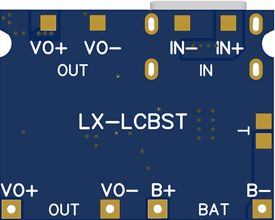
Pin Configuration and Descriptions

The LX - LCBST typically comes in a TO-220 package with the following pinout:

Pin Number Pin Name Description
1 VIN Input voltage pin. Connect to the power source.
2 GND Ground pin. Connect to the circuit ground.
3 VOUT Output voltage pin. Connect to the load.
4 ENABLE Enable pin. High to activate the booster.

Usage Instructions

The LX - LCBST is straightforward to use in a variety of circuits. Below are the steps and considerations for integrating it into your design:

How to Use the Component in a Circuit

  1. Power Input: Connect the VIN pin to a DC power source within the specified input voltage range (5V to 30V).
  2. Ground Connection: Connect the GND pin to the ground of your circuit.
  3. Load Connection: Connect the VOUT pin to the load that requires boosted current.
  4. Enable Pin: If the ENABLE pin is available, ensure it is pulled high to activate the booster. You can use a microcontroller or a pull-up resistor for this purpose.

Important Considerations and Best Practices

  • Heat Dissipation: The LX - LCBST can dissipate significant heat under high current loads. Use a heatsink with the TO-220 package to prevent overheating.
  • Input Voltage: Ensure the input voltage is within the specified range to avoid damage to the component.
  • Output Filtering: Add a capacitor (e.g., 100µF) at the output to reduce noise and improve stability.
  • Current Limiting: If your load requires less current than the maximum output, consider adding a current-limiting resistor to protect the load.
  • Reverse Polarity Protection: Use a diode at the input to prevent damage from reverse polarity connections.

Example: Using LX - LCBST with an Arduino UNO

The LX - LCBST can be controlled using an Arduino UNO to enable or disable the booster. Below is an example circuit and code:

Circuit Setup

  • Connect the VIN pin to a 12V DC power source.
  • Connect the GND pin to the Arduino GND.
  • Connect the ENABLE pin to Arduino digital pin 7.
  • Connect the VOUT pin to the load (e.g., a motor or LED array).

Arduino Code

// Define the pin connected to the ENABLE pin of LX - LCBST
const int enablePin = 7;

void setup() {
  // Set the ENABLE pin as an output
  pinMode(enablePin, OUTPUT);

  // Activate the LX - LCBST by setting the ENABLE pin HIGH
  digitalWrite(enablePin, HIGH);
}

void loop() {
  // The booster remains active in this example
  // Add your logic here to control the ENABLE pin as needed
}

Troubleshooting and FAQs

Common Issues and Solutions

  1. No Output Current:

    • Cause: The ENABLE pin is not properly connected or set to HIGH.
    • Solution: Verify the ENABLE pin connection and ensure it is pulled high.
  2. Overheating:

    • Cause: Excessive current draw or insufficient heat dissipation.
    • Solution: Use a heatsink and ensure the load does not exceed the maximum current rating.
  3. Noise or Instability in Output:

    • Cause: Insufficient output filtering.
    • Solution: Add a capacitor (e.g., 100µF) across the output terminals.
  4. Component Damage:

    • Cause: Input voltage exceeds the specified range or reverse polarity connection.
    • Solution: Verify the input voltage and use a reverse polarity protection diode.

FAQs

Q1: Can the LX - LCBST be used with AC input?
A1: No, the LX - LCBST is designed for DC input only. Use a rectifier circuit to convert AC to DC before connecting.

Q2: What is the maximum load the LX - LCBST can handle?
A2: The component can handle up to 10A of output current, provided proper heat dissipation is ensured.

Q3: Can I use the LX - LCBST for battery charging?
A3: Yes, it is suitable for battery charging applications. Ensure the output voltage and current are within the battery's specifications.

Q4: How do I disable the booster?
A4: Pull the ENABLE pin low (connect to GND) to disable the booster.

By following this documentation, you can effectively integrate the LX - LCBST into your electronic projects and ensure optimal performance.